K40 RAMPS Conversion
###Safety warning: lasers are capable of burning and blinding you, and the K40 units come with no safety interlocks. Add some safety switches to the interlock loop line (P1-P2 in the diagram below) so that when not actuated by the lids being closed on them, they interrupt the line. A water flow switch in the interlock loop is a good idea too so the laser won't operate if the coolant loop is not running. I've also heard of some units coming improperly grounded so make sure you inspect the power system fully, the ground pin of the 110V IEC jack should show continuity with the chassis of the power supply inside, and the chassis of the unit as a whole.
First off I'd like to thank Jeremy of Weistek Engineering and Dan of 3dprintzothar for their documentation that made this so easy for me. Also thanks to TurnkeyTyranny for the software to make this possible.
You'll want a breakout board for the ribbon cable in your cutter (the ribbon cable carries the X/Y endstop signals as well as the lines to the X axis stepper), and a connector for the cable. You can remove the connector from your Moshidraw board, or grab a new one from Digikey.
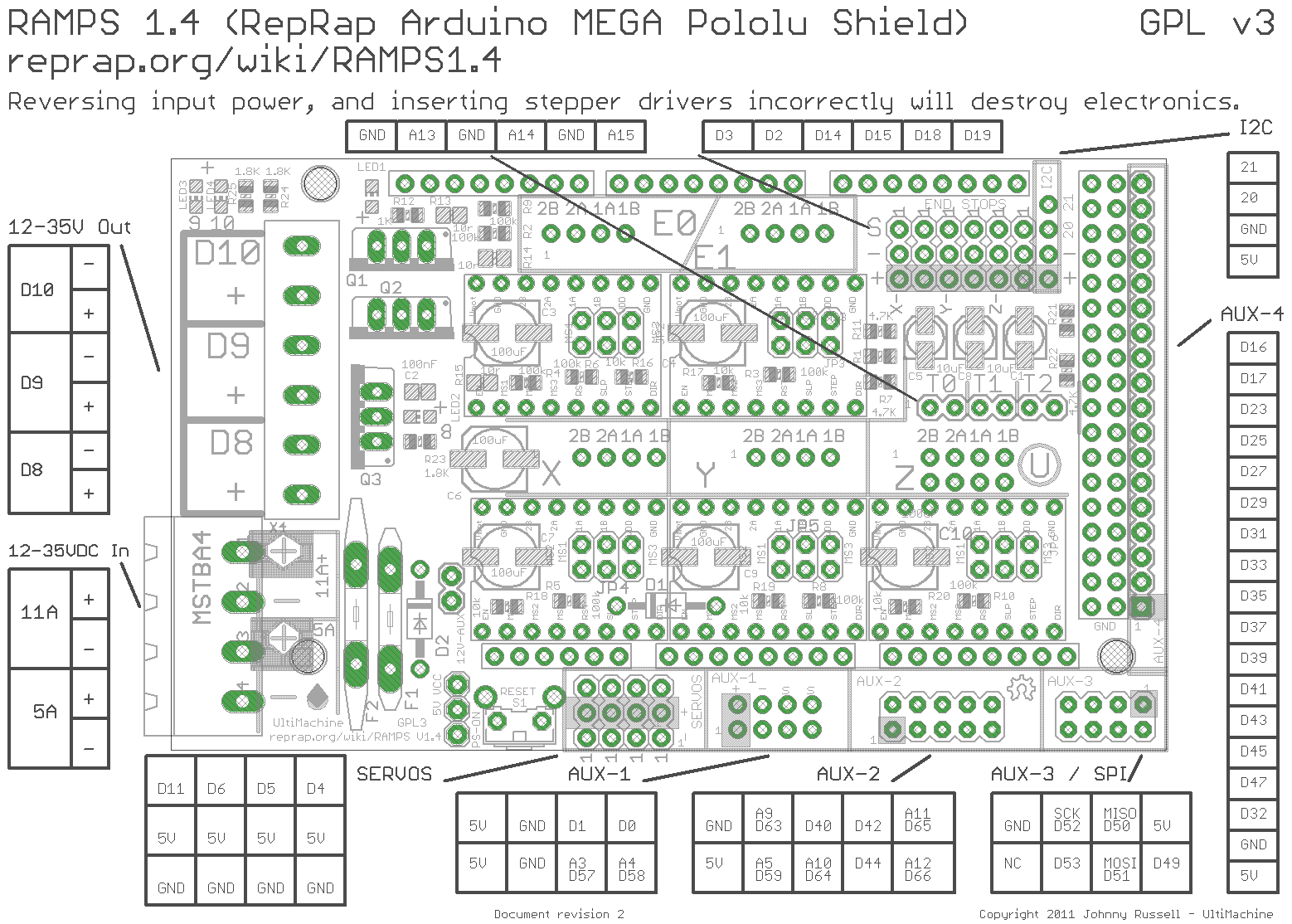
The RAMPS board itself will need a couple of modifications. Remove D1 from under the X/Y axis driver modules (this is normally used to drop the 12V input to 5V for the Arduino, but since we're feeding the stepper drivers with 24V this won't work). Also remove the big poly fuses F1 and F2 next to the green terminal blocks and then short their pins (I soldered in a few chunks of solid copper wire). Remember to set the jumpers for whatever microstepping you want, and double-check the orientation of the Pololu driver modules when you pop them into the RAMPS.
I printed out a dimensional drawing of an Arduino Mega, taped it to the Moshidraw board bracket, and marked off new mounting holes. A few minutes with my drill press, some screws and standoffs, and I had the Mega mounted to the bracket. I added the RAMPS board and then stuffed it back into the laser's electronics bay.
Interconnects!

So, a list of what you need to connect:
+24V from power supply to the 5A input on the RAMPS (bottom left corner)
Ground from power supply to the 5A input on the RAMPS (bottom left corner)
+5V from power supply to the +V pin on the I2C pin row (top, near the right edge)
Laser fire from the power supply to servo D5 on the RAMPS (bottom edge, near left)
Laser PWM from the power supply to servo D6 on the RAMPS (bottom edge, near left)
RAMPS to Y-axis stepper:
Y2B - White
Y2A - Yellow
Y1A - Blue
Y1B - Red
RAMPS to middleman board:
X2B - XA
X2A - XA+
X1A - XB
X1B - XB+
X endstop +V - 5Vin
X endstop gnd - GND
X endstop signal - EStX
Y endstop signal - EStY
For all the connections other than +24V/gnd to the power supply, I used male-to-female header jumper wires. The female ends slip over the pins on the RAMPS just fine, and the male ends make a nice positive connection in the screw terminals on the power supply. RAMPS to Middleman were female-female jumpers, and I soldered male pins onto the Middleman board. I only populated the stepper, estop, and 5Vin/GND pins.
Software! The Turnkey K40 Laser Arduino + Ramps Firmware with these values changed in configuration.h:
#define DISABLE_X true
#define DISABLE_Y true
#define Y_HOME_DIR 1
#define X_MAX_POS 330
#define MANUAL_Y_HOME_POS 230
Those settings will shut off power to the steppers when they're not being actively driven (so you can push them out of the way, be sure to re-home after!), defines the Y axis homing switch to be at the max position rather than the minimum, drops the X axis size a little bit (the default caused the head to crash in mine), and defines the Y home position to be at the Y axis max travel.
To create gcode for the RAMPS, TurnkeyTyranny also has an Inkscape plugin. Although the K40 homes to the top left, the Y axis origin is on the bottom (so it actually homes to 0,230). As a result in the gcode exporter, make sure you select "Bottom Left" for the Y-Axis Origin drop-down.
I've not done much yet in the way of determining cut speeds and power. One thing, make sure to always keep an eye on your current meter, it shouldn't exceed 21-22mA, otherwise you'll burn out your laser tube very quickly. Rather than crank up the power, try slowing your feed rate. An air assist nozzle helps a lot, I used this one from Lightobject along with this air pump.
The included ventilation fan and ducting is pretty ineffective. I grabbed a 4" dust hood that slides perfectly into the exhaust duct slot on the back of the laser, a 4" flexible hose, a 4" to 6" adapter, and a 6" inline duct fan. Right now I just stick the fan outside the garage door when the laser is running but I plan to run ductwork up to a hood on the roof, and maybe put in an inline fume filter too.
The cutting bed it comes with also isn't so great. I removed the clamp-thing in the middle of the bed and grabbed a 12"x12"x0.5" square of aluminum honeycomb from eBay, right now I have it just resting on top of the stock cutting bed. I'd like to mount it to some L-brackets to provide surfaces I can butt materials up against, but haven't gotten to that yet. As a bonus the added .5" thickness of the honeycomb seems to be about right for focal length with the Lightobject air assist nozzle/lens/mirror assembly.
And because everyone likes pictures, here are some I took of my setup on Flickr.
And a video
