https://github.com/JChristensen/PowerOutageMonitor_SW
README file
Jack Christensen
2012
Arduino Power Outage Logger Copyright (C) 2012-2019 by Jack Christensen GNU GPL v3.0
This program is free software: you can redistribute it and/or modify it under the terms of the GNU General Public License v3.0 as published by the Free Software Foundation.
This program is distributed in the hope that it will be useful, but WITHOUT ANY WARRANTY; without even the implied warranty of MERCHANTABILITY or FITNESS FOR A PARTICULAR PURPOSE. See the GNU General Public License for more details.
You should have received a copy of the GNU General Public License along with this program. If not, see https://www.gnu.org/licenses/gpl.html
An Arduino sketch to implement a Power Outage Logger using the Microchip MCP79411 or MCP79412 RTC. Up to seven outages (power down/up times) can be logged in the RTC's SRAM.
The normal display is a clock showing time, date, and the number of power outages logged in angle brackets, e.g. <4>. After a new power outage, the New Outage alert LED is illuminated. Viewing the outage log turns the LED off. The clock adjusts automatically for daylight saving time.
Four buttons control the logger and are labeled:
SET / CLEAR / CANCEL(+) / FIRST / NEXT(-) / LAST / PREVRESET
From the clock display:
-
Press (+) or (-) to view the outage log. Pressing (+) will show the first (earliest) outage, pressing (+) again will show the next outage. Pressing (-) will show last (most recent) outage, pressing (-) again will show the previous outage. Press SET to return to clock mode, or it will automatically return after 30 seconds.
-
Press SET to begin the set sequence. Press (+) and (-) to adjust each parameter, hold to adjust rapidly. Press SET to advance to the next parameter. Hold SET to cancel the set sequence. Pressing (+) and (-) simultaneously while setting either the seconds or the RTC calibration will zero the value.
-
From clock mode or while viewing the outage log, hold SET to clear the outage log.
-
While in normal clock display mode, pressing and holding the (-) button will toggle Sunrise/Sunset mode, where sunrise and sunset times alternate with the date.
-
After pressing and releasing RESET, the RTC Sync message (with the RTC ID) and the Calibration message shown during startup can be held by pressing and holding the SET button.
-
Photocell test mode displays the photocell reading in place of the time zone. This can be useful to help calibrate display brightness. To invoke:
- Press and hold RESET and SET simultaneously.
- Release RESET.
- Continue holding SET until the New Outage LED goes out, then release.
Fuse settings are the same as Arduino Uno except 4.3V BOD, e.g.:
avrdude -p m328p -U lfuse:w:0xff:m -U hfuse:w:0xde:m -U efuse:w:0x04:m -v
An optional MCP9800/1/2/3 temperature sensor can be included on the I2C bus. If present, it will be automatically detected, and the temperature will be displayed on the LCD with the time.
A circuit schematic and PC board for this project is available at https://github.com/JChristensen/PowerOutageMonitor_HW
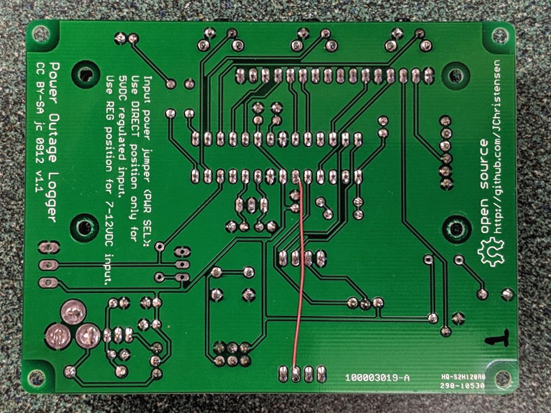
Instead of using the (perhaps more common) setSyncProvider() function in the Time library, the current code uses a 1Hz interrupt from the RTC to keep time. This has become my preferred method, but that was not the case when I designed the power outage logger board.
Therefore a wire is needed on the back of the board to provide the interrupt signal to the MCU. Connect a wire from the RTC "MFP" pin to the ATmega328P pin 6 (a.k.a PD4 or the Arduino D4 pin) as shown in the photo below. (Board version 1.2 includes this connection; therefore a wire is not necessary.)