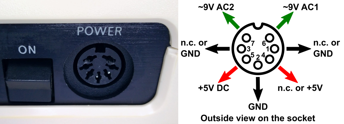
The old "power bricks" that supply the Commodore C64 lose their reliability over time and can then damage the device through overvoltage. The C64 Power Guard is connected between the power supply and the C64, it monitors the voltage and current on the 5V DC rail and immediately disconnects if an overvoltage or overcurrent occurs. It thus makes a valuable contribution to protecting your old hardware.
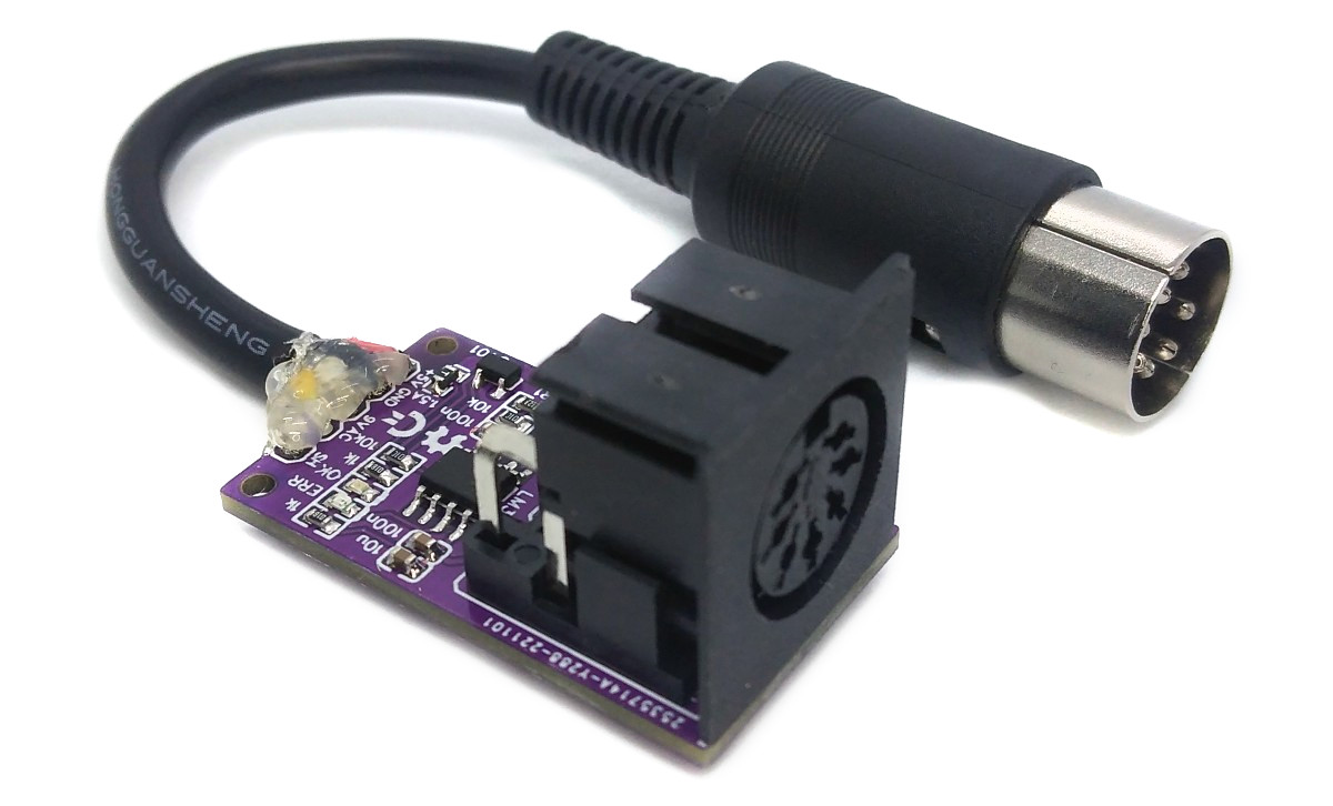
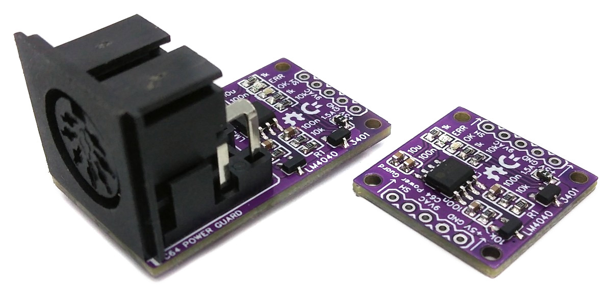
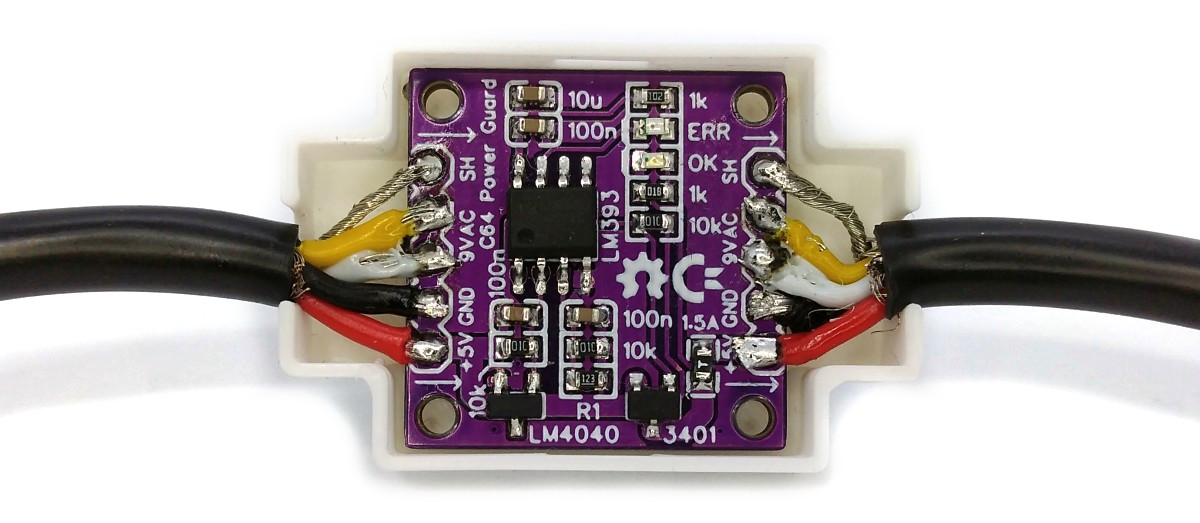
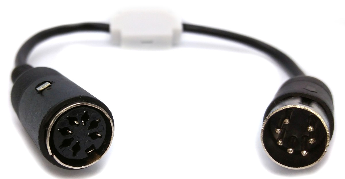
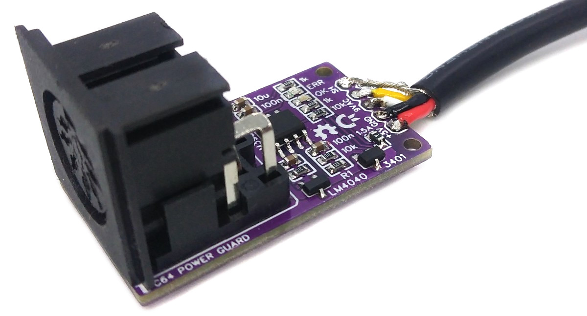
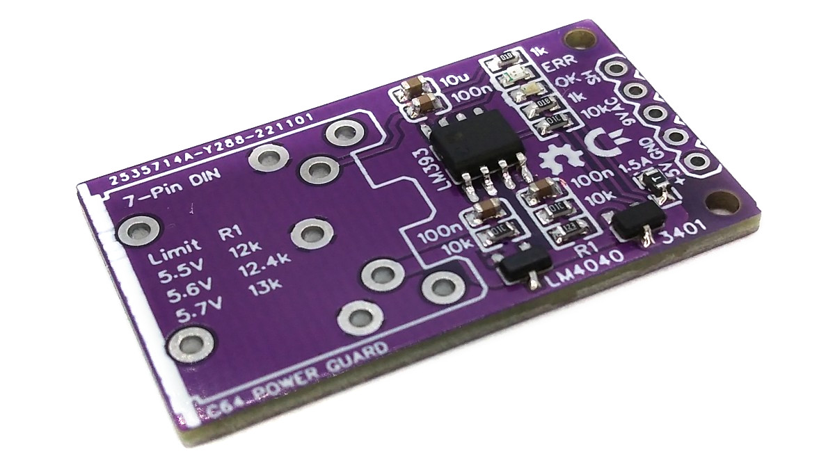
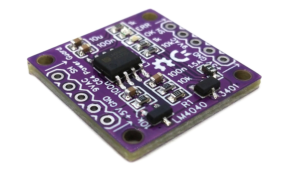
Two PCB versions are available. One version allows a 7-pin DIN input socket to be soldered directly onto the PCB, while the other has solder pads for both the input and output lines so that cable-type connectors can be soldered here.
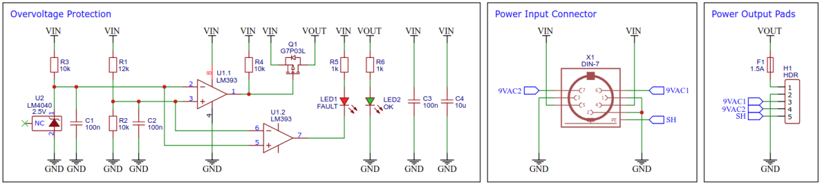
The LM393 comparator constantly compares the input voltage via a voltage divider with the LM4040 reference voltage (2.5V). As soon as the divided voltage is above the reference voltage, the power supply is disconnected via a P-channel MOSFET. The upper voltage limit for the 5V DC power rail is set via the resistors R1 and R2 of the voltage divider:
The 1.5A resettable fuse interrupts the power connection if an excessive load occurs, e.g. in the event of a short circuit. As a rule, a C64 does not consume more than 1.5A on the 5V DC power rail, but if required (e.g. when operating additional modules on the C64), a higher current value of the fuse can also be selected. If a fuse is not required, a 0Ω resistor can be soldered in instead or the contacts can simply be shorted with a solder bridge.
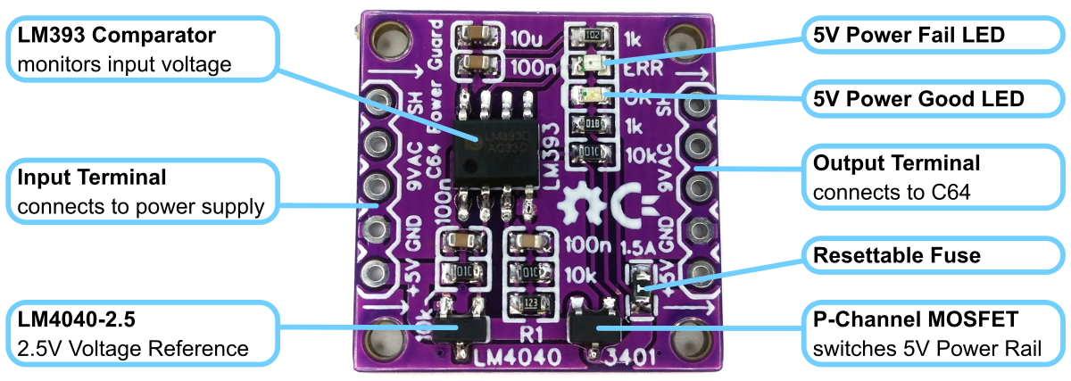
A P-channel MOSFETs is required to switch the DC power connection. In principle, all logic level P-channel MOSFETs are suitable, provided they meet the following conditions:
- must be in the SOT-23-3 package,
- Drain-Source Voltage must be at least
, - Gate-Source Voltage must be at least
, - Continuous Drain Current must be at least
, - Gate Threshold Voltage must not exceed
.
The values referred to are usually given as negative values for P-channel MOSFETs. In addition, care should be taken to ensure that the On-Resistance
An excellent choice is the G7P03L with an on-resistance of 23mΩ@-4.5V. If this is not available, an AO3401A with an on-resistance of 64mΩ@-4.5V will also do.
Before use, test the C64 Power Guard for proper operation using a variable power supply and a multimeter. Connect the input of the C64 Power Guard to the power supply. When the POWER GOOD LED lights up, the output can be connected to the C64 and it can be switched on safely.
- LM393 Datasheet
- LM4040 Datasheet
- G7P03L Datasheet
- AO3401A Datasheet
- 7-Pin DIN Connectors
- 1541-II Power Guard

This work is licensed under Creative Commons Attribution-ShareAlike 3.0 Unported License. (http://creativecommons.org/licenses/by-sa/3.0/)