The wiring of 2,4 GHz module might be different than the standard module. Please refer to the datasheet of your module.
Create a remote camera trap using LoRa.
This project uses LoRa to transmit an image captured by ESP32-CAM. Image is then stored on an SD card on the receiver side and displayed on a web server hosted on the receiver. Transmission time varies between 1 to 30 minutes (HD image), based on bandwidth and spread factor. Higher bandwidth means higher data rate, but shorter range. In order to achieve ideal transmission range, both sender and receiver must be in a line of sight. Only OV2640 camera module is currently supported. This is the one that comes with your ESP32-CAM by default.
1x ESP32-CAM
1x FTDI adapter for ESP32-CAM
1x DOIT DevKit V1 ESP32
2x SX127x LoRa transceiver module (make sure you get the correct frequency band for your region)
1x SD card reader module
1x PIR motion sensor
1x I2C LCD display (optional)
3x Breadboard
some jumper wires and solder
Pinouts:
SENDER:                                                             RECEIVER:
___________________________                                         ______________________
SX1278:           ESP32-CAM:                                        SX1278:          ESP32:
GND               GND                                               GND              GND
NSS               15                                                NSS              15
MOSI              13                                                MOSI             13
MISO              12                                                MISO             12
SCK               14                                                SCK              14
VCC               3V3                                               VCC              3V3
RST               not connected                                     RST              4
DIO0              2                                                 DIO0             2

PIR:                                                                I2C LCD:
data              3                                                 GND              GND
3V3               VCC                                               5V               VIN
GND               GND                                               SDA              21
                                                                    SCL              22
FTDI:
GND               GND                                               SD Card reader:
5V                5V                                                GND              GND
RX                U0T(1)                                            MISO             19
TX                U0R(3), only connect while flashing               SCK              18
                                                                    MOSI             23
                                                                    CS               5
                                                                    3V3              3V3


You must attach an antenna to you LoRa modules, otherwise you are risking damage to the modules. A piece of insulated wire will do, but adjust the length to the frequency of your module. Antenna should be quarter or half a wavelength long. I have used quarter a wavelength, that is 8,63 cm (in case of 868 MHz).
First you will need to install the following libraries:
SPI.h
SPIFFS.h
SD.h
LoRa.h
WiFi.h
LiquidCrystal_I2C.h
ESPAsyncWebServer.h
ESPAsyncTCP.h
EEPROM.h
time.h
esp_camera.h
In order to use ESP32 boards on your Arduino IDE, go to file/preferences/settings and add this URL to Additional boards URL: https://raw.githubusercontent.com/espressif/arduino-esp32/gh-pages/package_esp32_index.json Next, in tools/board/boards manager install the ESP32 package.
Board name is DOIT ESP32 DEVKIT V1.
First, type in the WiFi credentials.
const char* ssid = "SSID";
const char* password = "password";
In case you want to create a soft access point, uncomment softAP() in setup(), and comment wifiConnect().
As a next step, change the ntp server to fit your region in setup(). First parameter is time shift in seconds.
configTime(7200, 0, "your.ntp.server");
You may want to change LoRa bandwidth and spread factor as well, which are set to 500kHz, and 7 by default. In that case, you will need to do the same changes on sender module too, otherwise you will not receive any packets! These parameters can also be configured on the webpage, where the boards will be configured automatically. More on that later.
To upload code, push the BOOT button on your board as soon as you see dots and underscores, and release it after the board starts booting. After board initialization, connect to IP address printed by the serial monitor. You should see this page:
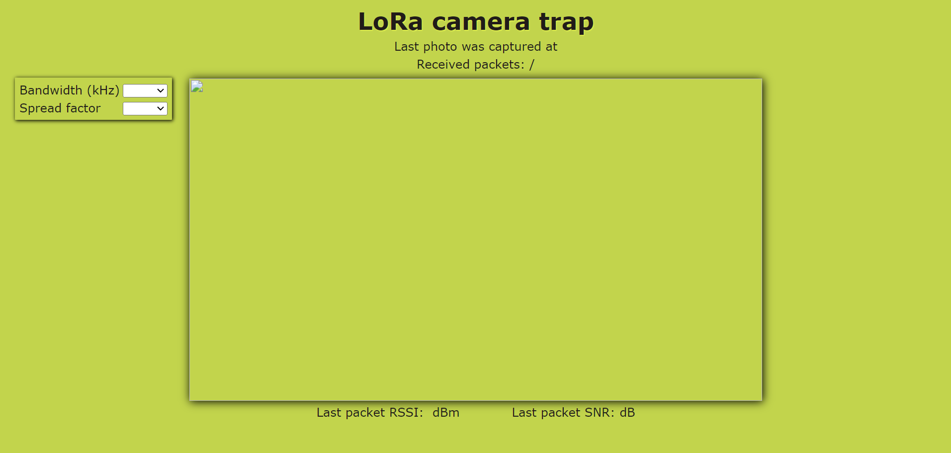
Values are empty, because no photo has been captured yet. In order to do so, let's set up the sender module.
Board name is AI THINKER ESP32-CAM.
The sender is ready without changing anything, but you may want to change picture resolution in setup(), which is HD by default. In that case, replace
config.frame_size = FRAMESIZE_HD;
by one of the following values:
FRAMESIZE_UXGA (1600 x 1200)
FRAMESIZE_SXGA (1280 x 1024)
FRAMESIZE_XGA (1024 x 768)
FRAMESIZE_SVGA (800 x 600)
FRAMESIZE_VGA (640 x 480)
FRAMESIZE_CIF (352 x 288)
FRAMESIZE_QVGA (320 x 240)
I have not adjusted the image holder on the webpage to contain images of other resolutions than HD, so they may not be displayed correctly. They will however be stored correctly on the SD card.
You can also change other camera settings, but I won't go into detail on that.
In order to upload code to ESP32-CAM, connect the FTDI adapter accoring to the pinout. Then connect GPIO0 to GND, and press the reset button as soon as you see dots and underscores. After you are done, disconnect GPIO0 from GND and connect PIR module according to the pinout. Press reset button once more.
After both devices are set up, wave your hand in front of the PIR sensor, to trigger motion detection. You should see changes on the webpage and LCD display. Image was taken and is now being transmitted. All values except image will now be automatically updated every 5 seconds. In order to update the image, refresh the page. Once the image is fully transmitted, it will stay on the screen until a new one is taken.
If you configure LoRa bandwidth or spreading factor on the webpage, changes will immediately take effect on the receiver. Since both the sender and the receiver need to be configured with the same bandwidth and SF, sender will stop receiving acknowledgment packets for a while, since reveicer is now using different parameters. The sender will sense this, and after not receiving any acknowldegment packet for a specified period (ack_wait_timeout) it will now periodically switch to various combinations of BW and SF, listening on the same variation for a period specified by SF_find_timeout. When an ack packet is received at a particular combination of BW and SF during this time window, the sender keeps these parameters and transmission continues normally.
Now this part is tricky. If SF_find_timeout is too short, no packet will be received because the time would be insufficient for a packed to be parsed. This is particularly obvious on low bandwidths and high spread factors. If SF_find_timeout is too long, it may take up to several minutes for a sender to finally find the correct combination of BW and SF. Tweak SF_find_timeout so that it suits your particular use scenario. At SF = 7 and BW = 500 kHz 500 ms is usually enough, but SF = 12 and BW = 7,8 kHz would need up to 30 seconds.
Here are some issues I came across while working on the project:
PROBLEM                                                               SOLUTION
1. LoRa won't initialize                                              Make sure the module is connected exactly according to the pinout.
2. Reciever is not getting any packets                                Make sure both modules are configured with the exact same bandwidth, spread factor, and coding rate. Keep the RSSI above -120 dBm and SNR above 0. Also don't forget to trigger the motion sensor!
3. Pictures are too brigth                                            Move the camera out of direct sun, or take extra dummy pictures before transmitting. Adjusting camera settings might help as well.
4. There is no photo on the webpage, even if new packets are coming   Refresh the page. If the problem persists, it means the initial packet was not received. Restart both modules and try again. Make sure you start the receiver before the sender, to make sure the initial packet is received.
5. Pictures contain horizontal stripes and weird discoloring          Some packets were lost. Increase bandwidth, decrease sprad factor, or decrease range.
6. Timestamp is shifted by a few hours                                Change the ntp server and adjust the time shift in configTime().
7. Transmission is stopped after changing bandwidth or SF             Increase value of _SF_find_timeout_ on the sender, up to 30000 ms.