LCD Driver Daughterboard
This daughterboard allows you to interface to many small touchscreen LCD modules.
Here is the daughterboard and partner Guzunty:
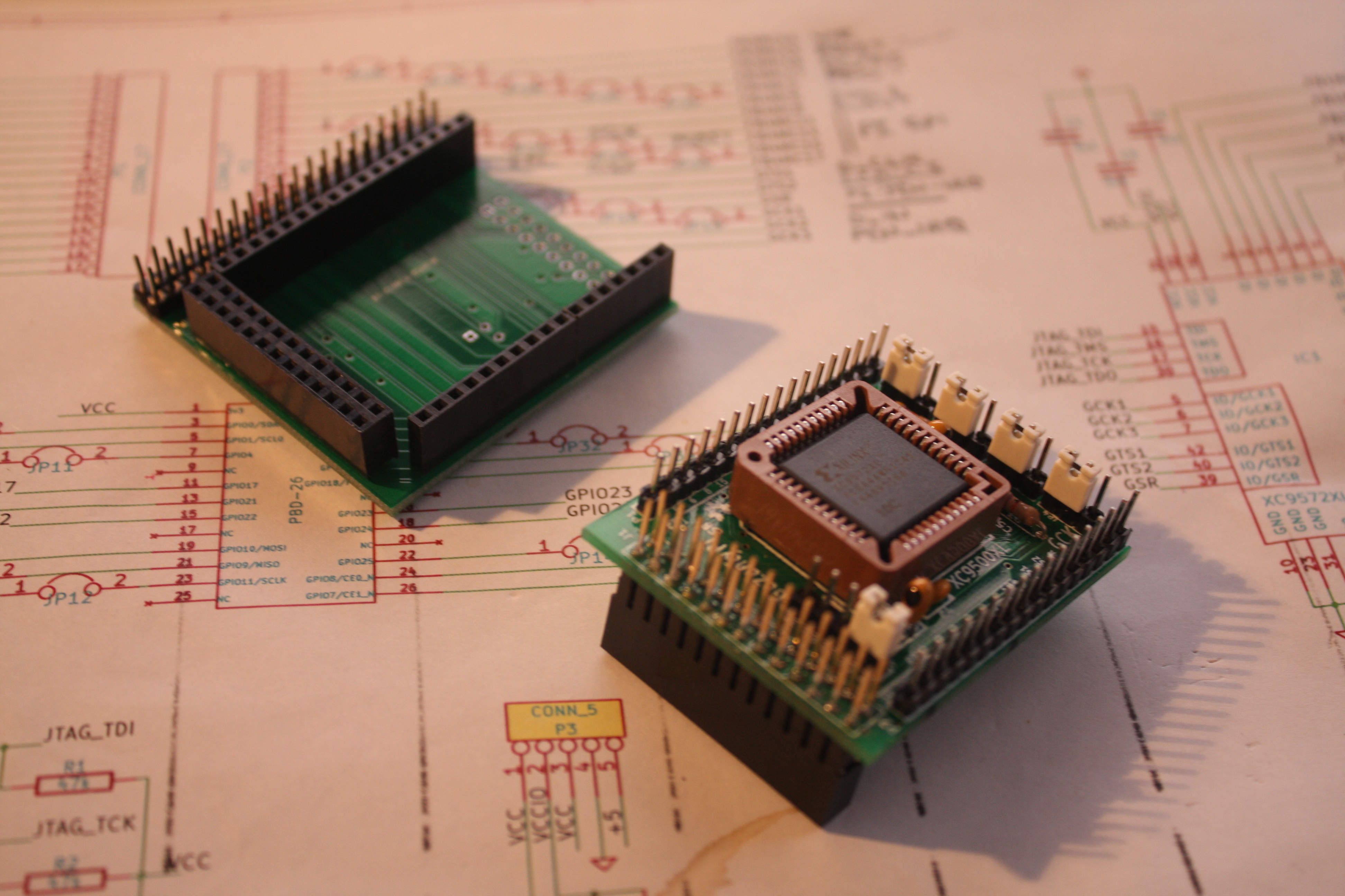
Note the long pins on the Guzunty Pi header socket that extend above the Guzunty PCB. The daughter card is shown upside down in this image so that its connectors are clearly visible.
Here is the Daughterboard mated with the Guzunty board ready for mounting on the Pi GPIO.

The ribbon cable is attached underneath the daughterboard to the 2x20 pin header array visible at the back in the top photograph.
Because the daughter card accesses the required Pi GPIO signals directly, no reconfiguration of the Guzunty is required.
Construction is straightforward. You do not need to populate P2 or P5, they are reserved for future expansion. Also, Q1 is unneeded. It is there to support a possible future brightness control. You do need to link the lower two pads of JP1 with a drop of solder (you would link the upper two pads to enable brightness control in the future). If you forget to do this you will have no backlight.
All connectors are populated on the lower side of the PCB and soldered on the upper side (the upper side is the one with the outline for the transistor).
