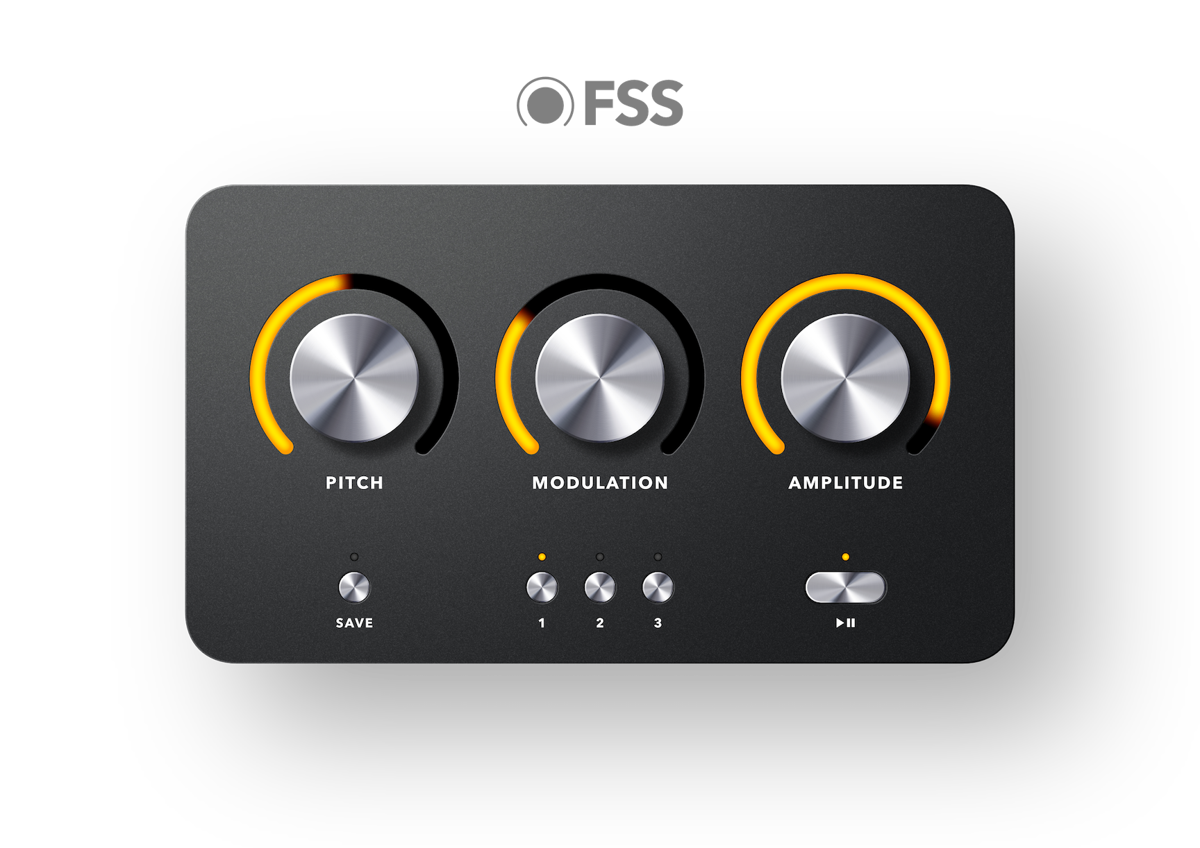
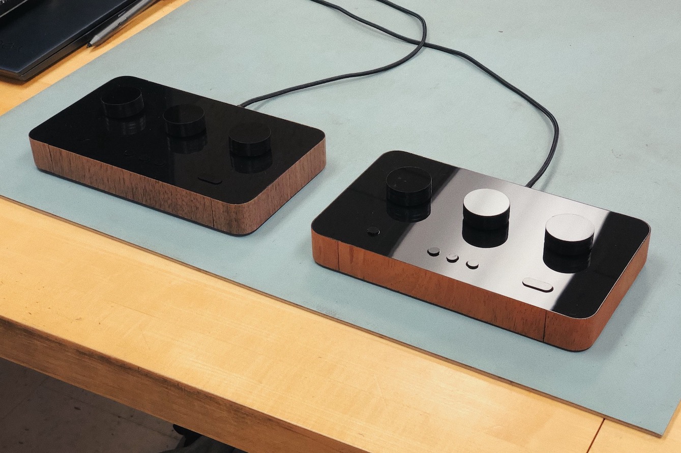
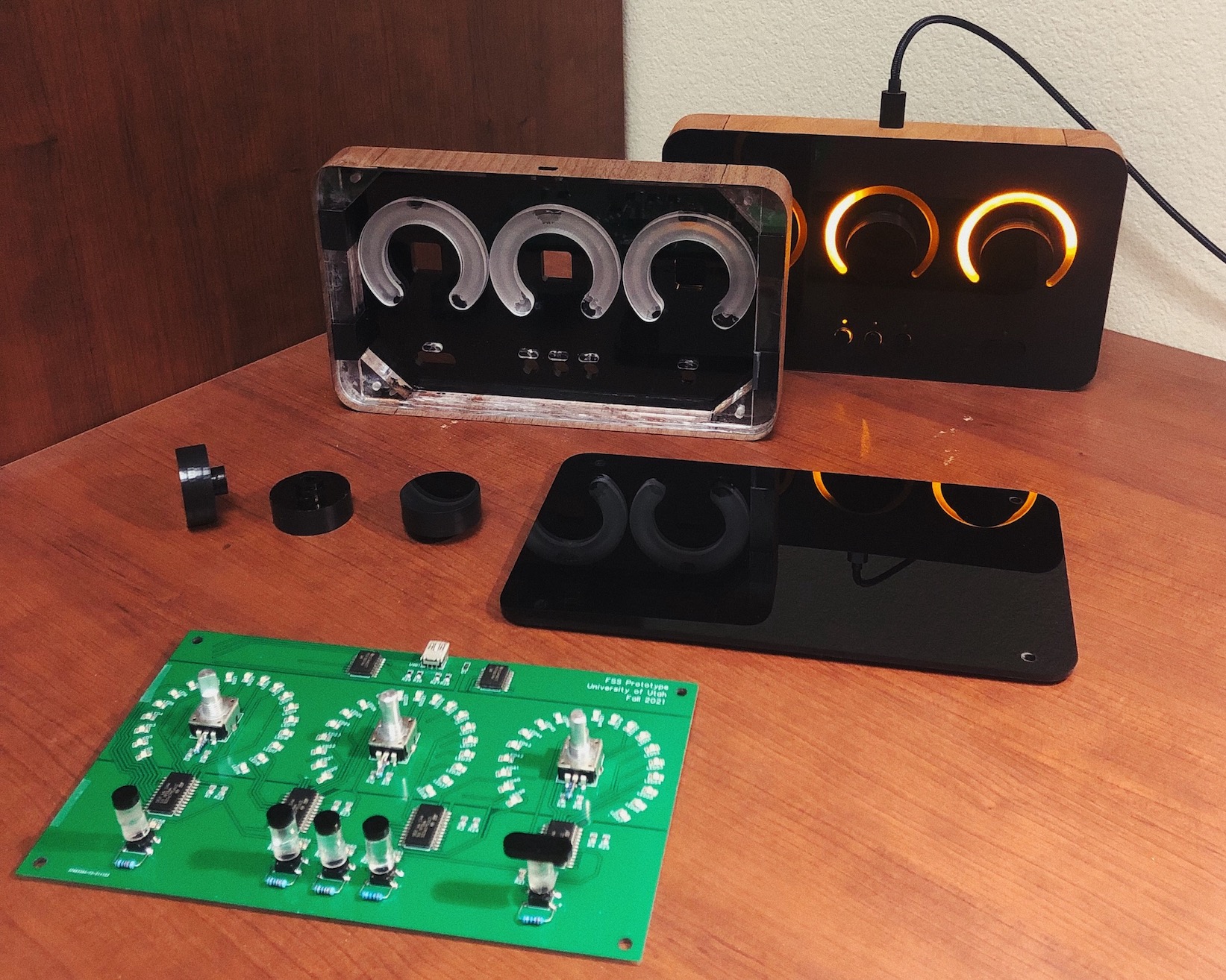
This FSS prototype demonstrates the future of interfacing with a music synthesizer. Musicians often switch between programs on their synth as part of their creative process when experimenting with different sounds. However, the control knobs on their synth can't dynamically update to visually display the true value of that knob when switching between programs. This FSS prototype solves this issue by providing program-synchronized ring displays surrounding control knobs, along with internal components housed in a beautiful chassis, and interfaced with via a single USB cable. This repository contains various source files, design files, datasheets, and documentation relevant to the development of this prototype. This prototype serves as the final project for the Computer Design Laboratory ECE 3710 class at The University of Utah for Group 2. As a requirement for this class, this final project uses the CompactRISC16 CPU and assembler that our group built as well. This CPU runs on an FPGA and executes our custom assembly code which is responsible for the FSS interface logic and communication. The FPGA board interfaces with the FSS prototype via I2C using a braided USB cable with the D+/D- pins adapted to be the SCL and SDA pins.
- Jacob Peterson
- Brady Hartog
- Isabella Gilman
- Nate Hansen
.formatter/verilog/contains the Verilog source code formatter. More info on it here.CompactRISC16/is a git submodule of our custom CompactRISC16 (CR16) processor repository. Our FSS prototype firmware runs on this custom CR16 processor.assets/contains various asset files such as SolidWorks sketches and parts, dimension drawings for laser and water jet cutting, schematic and PCB files for our Main board and External board, pictures, etc.docs/contains our final project reports and Bill of Materials (BOM). Our final report is located here.resources/bram_init/contains block RAM (BRAM) initialization files encoded in UTF-8 hexadecimal characters.resources/pin_assignments/contains exported CSVs of pin assignments for the various Verilog top modules in this repository.src/asm/contains assembly source code files written in accordance with our custom CR16 ISA. More info onfss.asm(the main program/firmware of our FSS prototype) can be found here.src/v/rtl/contains the Verilog and SystemVerilog RTL code for our FSS prototype.fss_top.svinstantiates BRAM, the External Memory interface module, and the CR16 processor. Additionally, it contains some logic to display various values on the 7-segment displays on the FPGA board and allows a user to address into BRAM using slide switches.ext_mem.svis the External Memory interface module which contains memory-mapping logic and instantiates the two peripherals that the FSS prototype requires:clock_divided_counter.svwhich is used as a microsecond counter andi2c_bus.svwhich is used to interface with the open-drain SCL and SDA bus lines for I2C communication.
src/v/tb/contains the Verilog and SystemVerilog testbench code for testing the various FSS prototype RTL modules.
We wanted to create a professional video in the form of a product advertisement showing the beauty we captured in the FSS prototype's design. That video is available here. Additionally, a demo video showing the basic usage and functional overview of the FSS prototype is available here.


Assembling fss.asm
fss.asm contains the assembly source code for the firmware of the FSS prototype. This assembly source code is compiled to a machine code data file which is loaded into BRAM upon FPGA programming. To assemble/compile fss.asm, follow these steps:
- Ensure that the
CompactRISC16submodule has been initialized and updated via:git submodule update --init - Run the assembler via:
./CompactRISC16/assembler/assembler src/asm/fss.asm -o resources/bram_init/fss.dat -p 4096 -v 0 -b HEX
-p 4096sets the max padding lines to 4096 (which is 2^12 due tofss_topinstantiatingbramwith a 12-bit address space) in the output machine code file-v 0sets the padding line value to 0 (which initializes empty BRAM to all zeros) in the output machine code file-b HEXsets the number base to hexadecimal in the output machine code file
- More info about the CR16 assembler used in this project can be found here.
- File names, module names, and wire/reg assignment names should be snake case (e.g.
my_verilog_module.v) - Testbench modules and file names should be appended with a
_tb(e.g.my_verilog_module_tb.v) - Top level modules and file names should be appended with a
_top(e.g.my_verilog_module_top.v) - There should only be one module per source code file
- Module instantiations should use uppercase named port lists with inputs prepended with
I_and outputs prepended withO_(e.g.my_verilog_module(.I_INPUT_1(my_input_1), .O_OUTPUT_1(my_output_1));) - Module signatures and bodies should use parameters instead of hard-coding constants. When defining the parameters for a module instantiation or for a module signature, the parameter list should start on the next line, but if there is only one parameter, it should be defined on the same line as the module instantiation or signature (same goes for the port list of a module).
- The port list in module signatures should contain
inputandoutputport direction declarations, as opposed to those port direction declarations being placed in the body of the module. - Consecutive single line comments should always be aligned with eachother if there are no lines between them.
- If there are 2 or more consecutive lines (including no comments between the consecutive lines) that assign a
parameter,localparam,wire, orregto a constant or to a single-line expression, then the equals signs in those lines should be aligned. - If a single-line expression/assignment needs to be split into multiple lines, then the following lines should be further indented by 8 spaces, or if the subsequent lines can fit within the 100 character column limit, then the subsequent lines should be further indented until they are aligned to the expression/assigment on the first line.
- No line should be greater than 100 characters.
- Use non-blocking assignments (e.g.
<=) in sequential@alwaysblocks and blocking assignments (e.g.=) in combinational@alwaysblocks.- An
@alwaysblock is sequential if it is sensitive to theposedgeornegedgeof an input signal, whereas it is combinational if it is sensitive to signals without theposedgeornegedgemodifier included in the sensitivity list.
- An
- Module sections should generally follow the following format, from top of file to bottom of file:
- Module signature with parameter list, then input wires, then output reg/wires
localparams that defines constants for the rest of the module- Internal register and wire declarations
- Prepend reg/wire names with
q_to represent a 'current state' register/wire andn_to represent a 'next state' register/wire
- Prepend reg/wire names with
- Output mapping
assignstatements which map internal wires/registers with module output wires/registers - RTL logic with
assignstatements for all internal wires which generally consist of ternary operators - Module instantiations using named port lists in the instantiation signature and a module instance name that is the same as the module name (or a name that's more concise and applicable to the instantiation), but with
iprepended - Clock
@alwaysblocks which generally should only includeposedge I_CLKin the sensitivty list - Other
@always(such as internal finite state machines) ortaskblocks
To format verilog source code, use the istyle-verilog-formatter tool via the format script:
.formatter/verilog/format <paths to files or directories>
For example, to recursively format Verilog source files in the src directory, use the following command:
.formatter/verilog/format src
The istyle-verilog-formatter is used as a submodule in the .formatter/verilog directory. Either clone this repository with git clone --recurse-submodules or use git submodule init; git submodule update to clone the istyle-verilog-formatter repository into the .formatter/verilog directory so that the format script can run properly. The format shell script will run make if the iStyle binary is not already present in the istyle-verilog-formatter directory. Note: you may need to make the script executable via: chmod 755 .formatter/verilog/format.