Board Geoffs Maximite
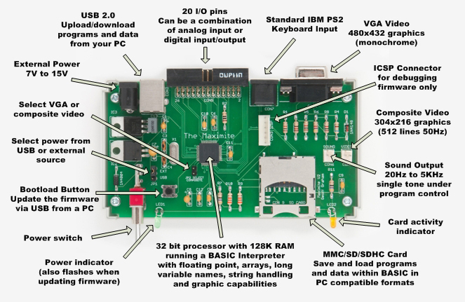
Maximite is a small single-chip BASIC computer, developed by Geoff Graham (schematics).
.png)
Features:
- Microchip PIC32MX795 microcontroller 80 MHz with MIPS architecture (datasheet)
- 40 usable i/o pins
- Compatible with Arduino shields
- USB 2.0 controller with mini-USB connector
- SD card connector at SPI4
- VGA port with monochrome output, 480 by 432
- PS/2 port for keyboard
- Battery-backed Real Time Clock (RTC) with I2C interface
- On-board oscillator 8 MHz
- Power select switch: from USB or from external source
- External power connector, 9-18 volts DC
- One power LED and one user LED
- User button
- User I/O port (13x2 header)
Memory:
- 512 kbytes of Flash memory
- 12 kbytes of additional boot Flash memory
- 128 kbytes of RAM
A notable drawback of Maximite is that none of UART or SPI ports is available on external connectors.
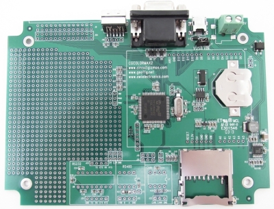
CGCOLORMAX2 is a clone of Maximite developed by CircuitGizmos (Programming Tutorial).
The board has space for RS-232, RS-485 and CAN interface circuits (not populated).
| Component | PIC32 |
|---|---|
| LED_D4 (green) | RE0 (93) |
| LED_D5 (blue) | RE1 (94) |
| Button | C13 (73) |
| Function | PIC32 | Pin | Pin | PIC32 | Function |
|---|---|---|---|---|---|
| Ground | 1 | 2 | Ground | ||
| AN15 | RB15 (44) | 3 | 4 | RE8 (18) | INT1 |
| AN14 | RB14 (43) | 5 | 6 | RA15 (67) | INT4, SDA1 |
| AN13 | RB13 (42) | 7 | 8 | RA1 (66) | INT3, SCL1 |
| AN12 | RB12 (41) | 9 | 10 | RE9 (19) | INT2 |
| AN0 | RB0 (25) | 11 | 12 | RG15 (1) | |
| AN1 | RB1 (24) | 13 | 14 | RE5 (3) | |
| AN2 | RB2 (23) | 15 | 16 | RC1 (6) | |
| AN3 | RB3 (22) | 17 | 18 | RC2 (7) | |
| AN4 | RB4 (21) | 19 | 20 | RC3 (8) | |
| AN5 | RB5 (20) | 21 | 22 | RA0 (17) | |
| +5V | 23 | 24 | +3.3V | ||
| Ground | 25 | 26 | Ground |
| Pin | PIC32 | Functions |
|---|---|---|
| D0 | RD8 (68) | |
| D1 | RD11 (71) | |
| D2 | RD12 (79) | |
| D3 | RD4 (81) | |
| D4 | RF0 (87) | |
| D5 | RF1 (88) | |
| D6 | RG1 (89) | |
| D7 | RG0 (90) | |
| D8 | RA6 (91) | |
| D9 | RA7 (92) | |
| D10 | RG14 (95) | |
| D11 | RG12 (96) | |
| D12 | RG13 (97) | |
| D13 | RE4 (100) | |
| A0 | RB8 (32) | AN8 |
| A1 | RB9 (33) | AN9 |
| A2 | RB10 (34) | AN10 |
| A3 | RB11 (35) | AN11 |
| A4 | RB7 (27) | AN7 |
| A5 | RB6 (26) | AN6 |
Chip DS1307 with I2C interface is connected to port SCL2/SDA2.
| Signal | PIC32 |
|---|---|
| SCL2 | RA2 (58) |
| SDA2 | RA3 (59) |