Hardware Build
End-to-end guide: from "the BOM has arrived" to "powered-on hub + tank."
The deep reference (schematics, pin maps, BOM, 3D STEP files) lives in the repo's
hardware/folder. This wiki page is the step-by-step tour.
- A hub (RX) plugged into a USB-C wall adapter, indoors, ~15 cm × ~10 cm × ~5 cm.
- One or more transmitters (TX), each mounted on the lid of a tank, solar-powered.
- Sensor cables going from each TX's enclosure down through its tank lid (field-cut to length).
Files: hardware/cases/circular-v1/ (TX) + your own hub case (we don't ship one yet — community designs welcome).
PETG, 0.2 mm, 30 % gyroid infill, 4 perimeters, ~80 °C bed, ~245 °C nozzle. Print supports for the top-with-solar piece (tree). See cases/README.md for full notes.
While prints are running, order PCBs.
Send the schematic SVG + project files to JLCPCB or PCBWay. 10 pieces is the minimum and works out to ~₹60 each. The PCBs arrive in ~10 days (express ~5).
We have a stretch-goal of publishing the EasyEDA project files publicly. For now, the schematic PNG/SVG + pin assignments are enough to recreate the design — see Wiring Reference (Hub) and Wiring Reference (Transmitter).
Use the Bill of Materials. Order 2× of everything, because the first one is the build, the second is the spare. SMD parts are cheap when you buy in bulk; the savings disappear if you have to re-order.
The PCBs are designed to be hand-solderable — no QFNs, no fine-pitch BGAs. SMD passives are 0805 / 0603 (manageable with a fine tip and tweezers). Use leaded solder if you're new to it; lead-free is harder.
Order of soldering:
- SMD passives (resistors, caps, diodes) first — easiest while the board is empty.
- THT (through-hole) buttons + screw terminals next.
- Modules (ESP32 module, RYLR998, INA219, MT3608, CN3791) last — they sit on female headers so you can pull them for debugging.
Test each subsystem before populating the next:
- Power chain — solder power section, plug in 18650, scope 3.3 V rail with a meter.
- UART — plug in RYLR998, power on, send
AT\r\nvia your USB-UART adapter. Expect+OK\r\n. - I²C — plug in INA219,
i2cdetect(over USB serial) finds0x40. - Sensor — wire JSN-SR04T (5 V power, TRIG/ECHO with divider), check
idf.py monitorshows distance values.
Easiest path: use the browser flasher.
For development: install ESP-IDF v5.5.2, then:
# Hub
cd firmware/Receiver-ESP32-DevKit
idf.py set-target esp32
idf.py build flash monitor

# Transmitter
cd firmware/Transmitter-IDF
idf.py set-target esp32c3
idf.py build flash monitor
The VERSION file in each firmware folder is the single source of truth — edit it once to bump versions.
Per cases/circular-v1/README.md:
- Heat-set M3 inserts into the four corners of the base (if using).
- Drop the populated PCB in, secure with the 18650 holder.
- Feed the sensor cable through the gland from outside; screw-terminal both ends.
- Mount the panel in the lid pocket; feed wires through the grommet; solder to PCB.
- Lay the EPDM gasket on the base rim; screw the lid down with 4× M3 stainless to moderate torque.
- Field-drill a hole in the tank lid for the BSP sensor-screw boss.
- Thread the boss through the lid from above. Tighten the nut from underneath. Teflon tape on threads for water seal.
- Sit the enclosure on the lid (solar panel facing the sun). Use M3 stainless screws if you want it fixed.
- Run the sensor cable from the enclosure's cable gland to the sensor-screw boss; screw-terminal both ends.
- The JSN-SR04T transducer head ends up ~20 mm below the lid's internal surface, pointing down at the water.
- Hub gets USB-C power. Setup mode → Wi-Fi config → MQTT config (cloud or local).
- TX gets solar + 18650. Hold BOOT 5 s → pairing.
- Confirm in the PWA / web UI.
See First Boot for what every step should look like.
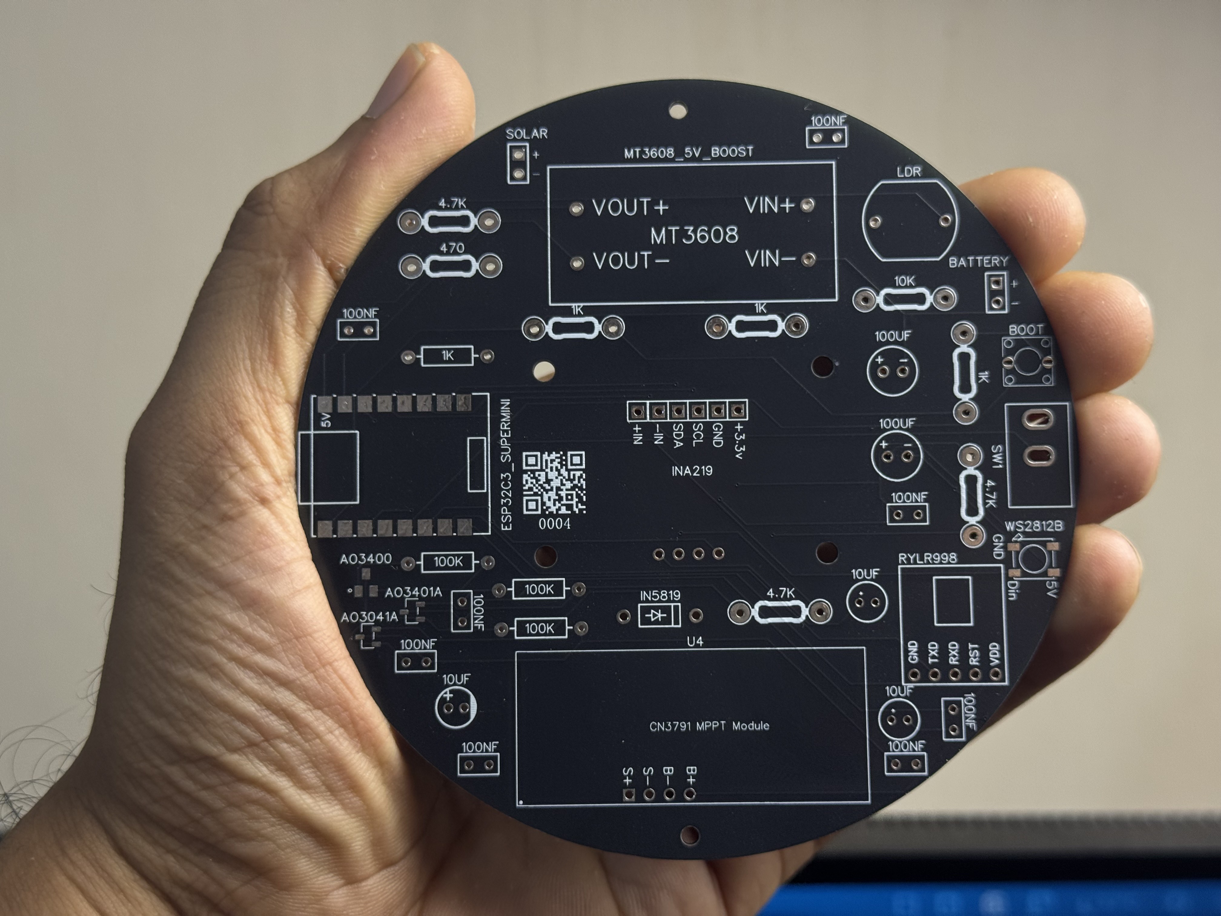
The TX board, fresh from the fab, ready to populate:
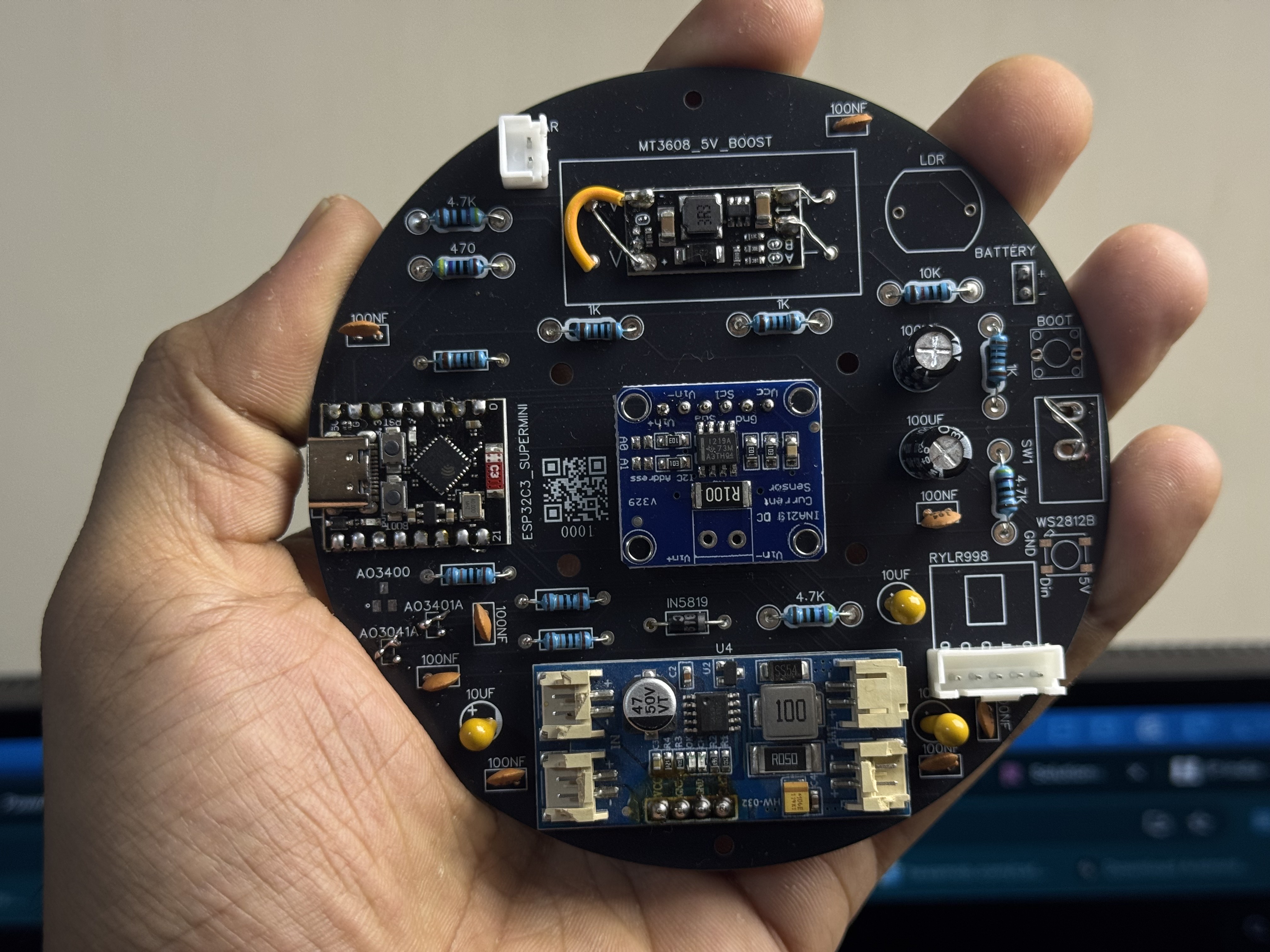
After hand-soldering — modules sitting on female headers so you can pull them for debugging:
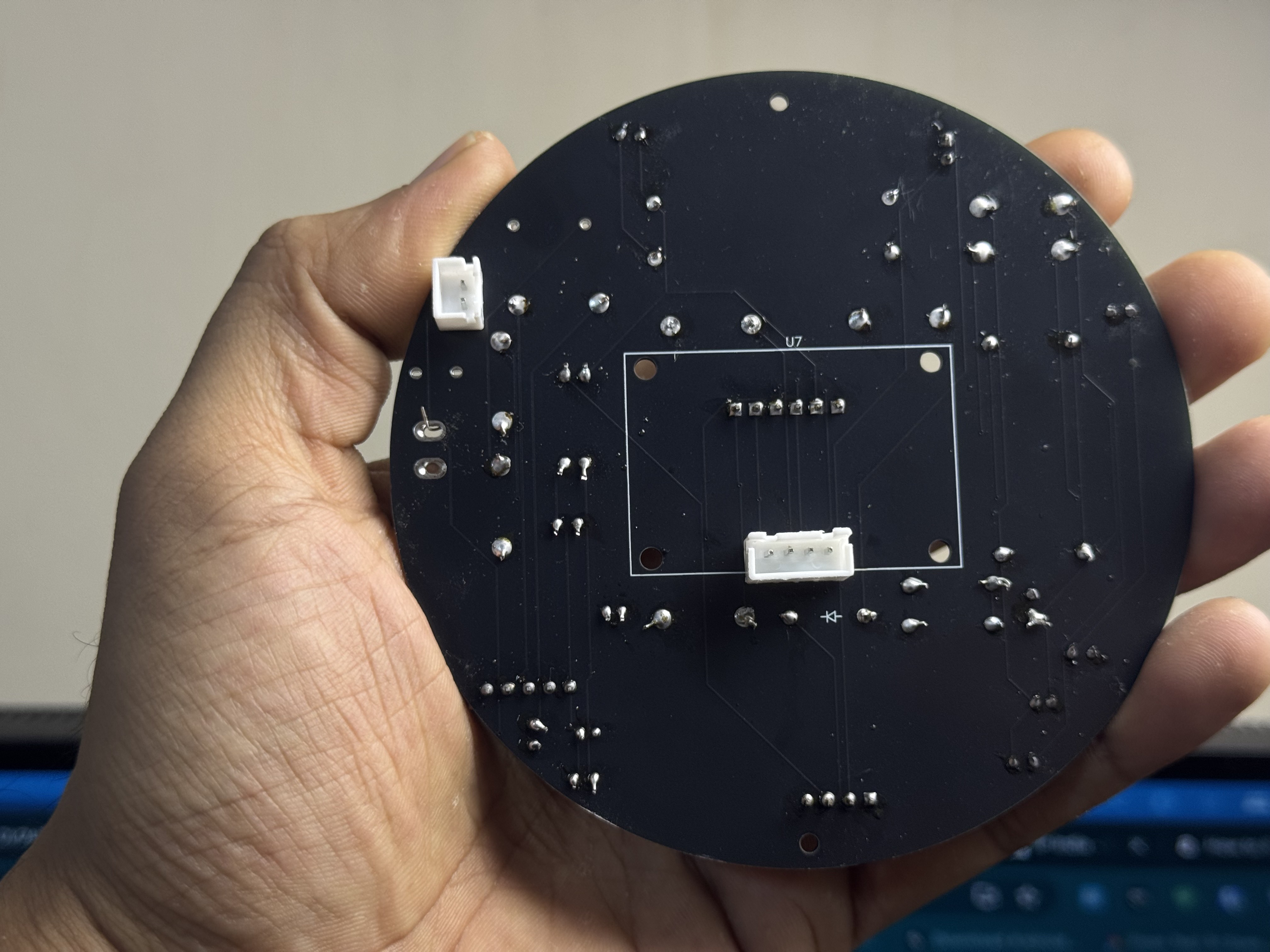
Back of the same board (passives + the inline Schottky on the battery rail):
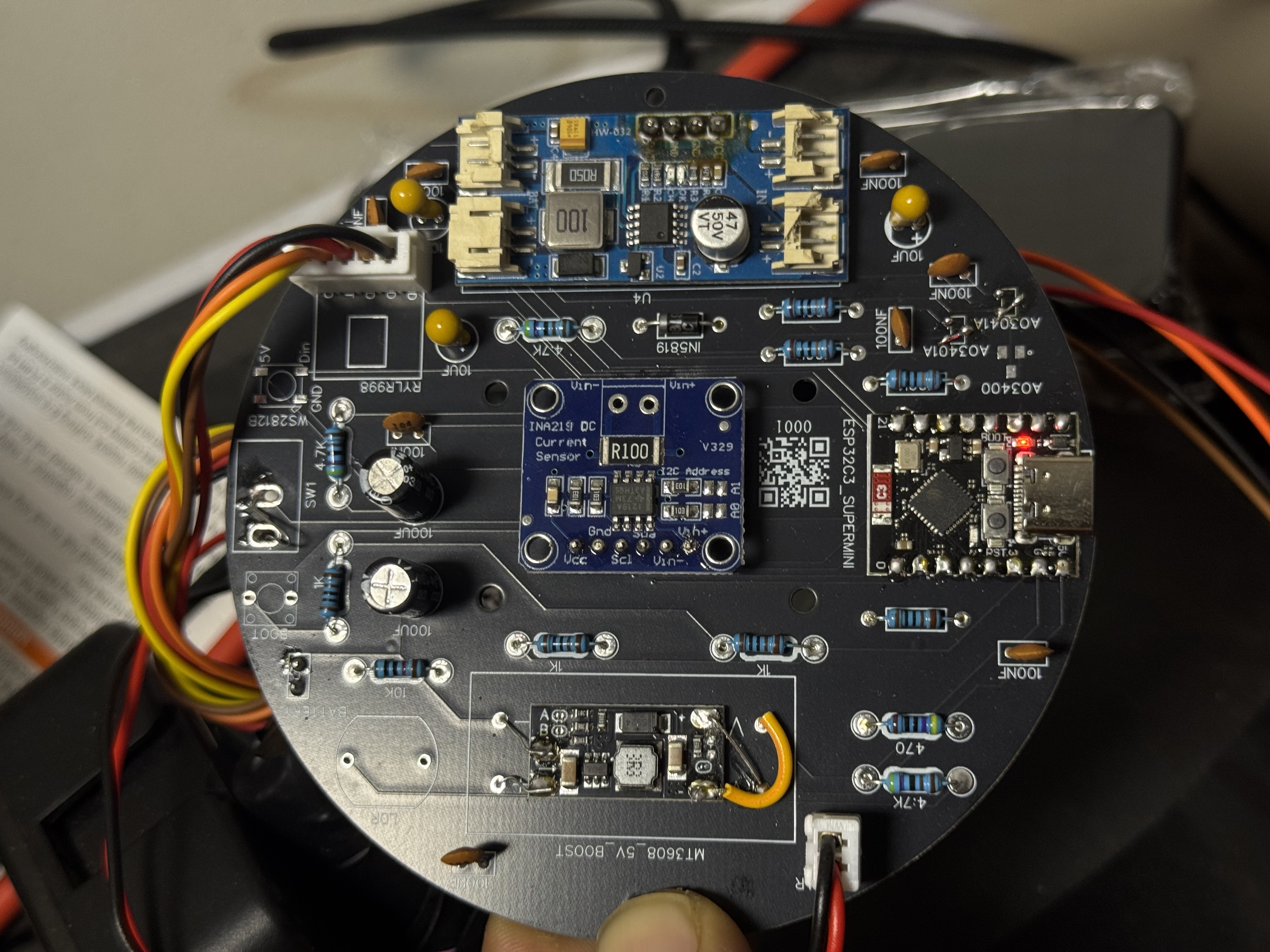
Angled view showing the whole module stack:
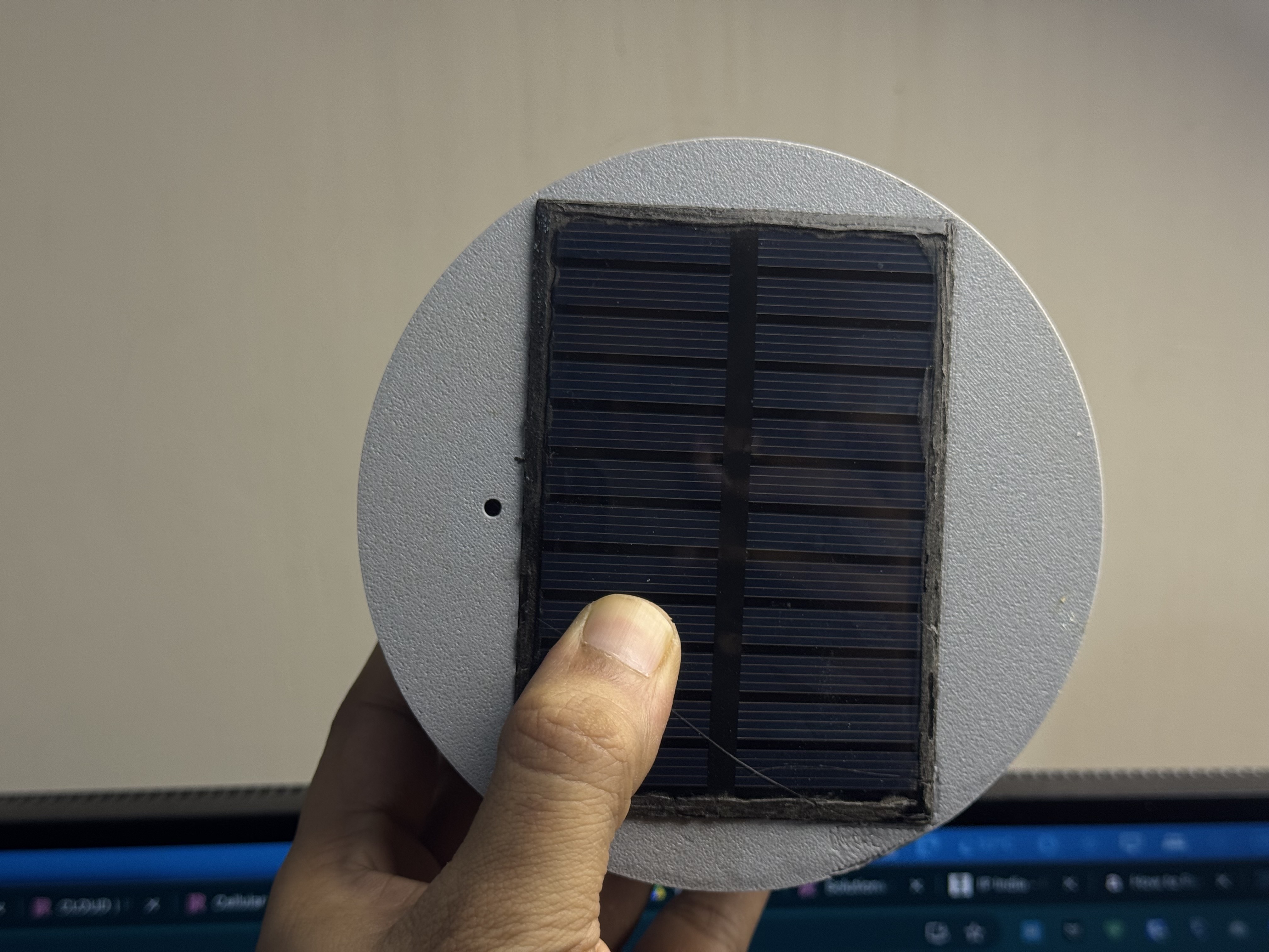
Lid half with the solar panel installed in the integrated pocket:
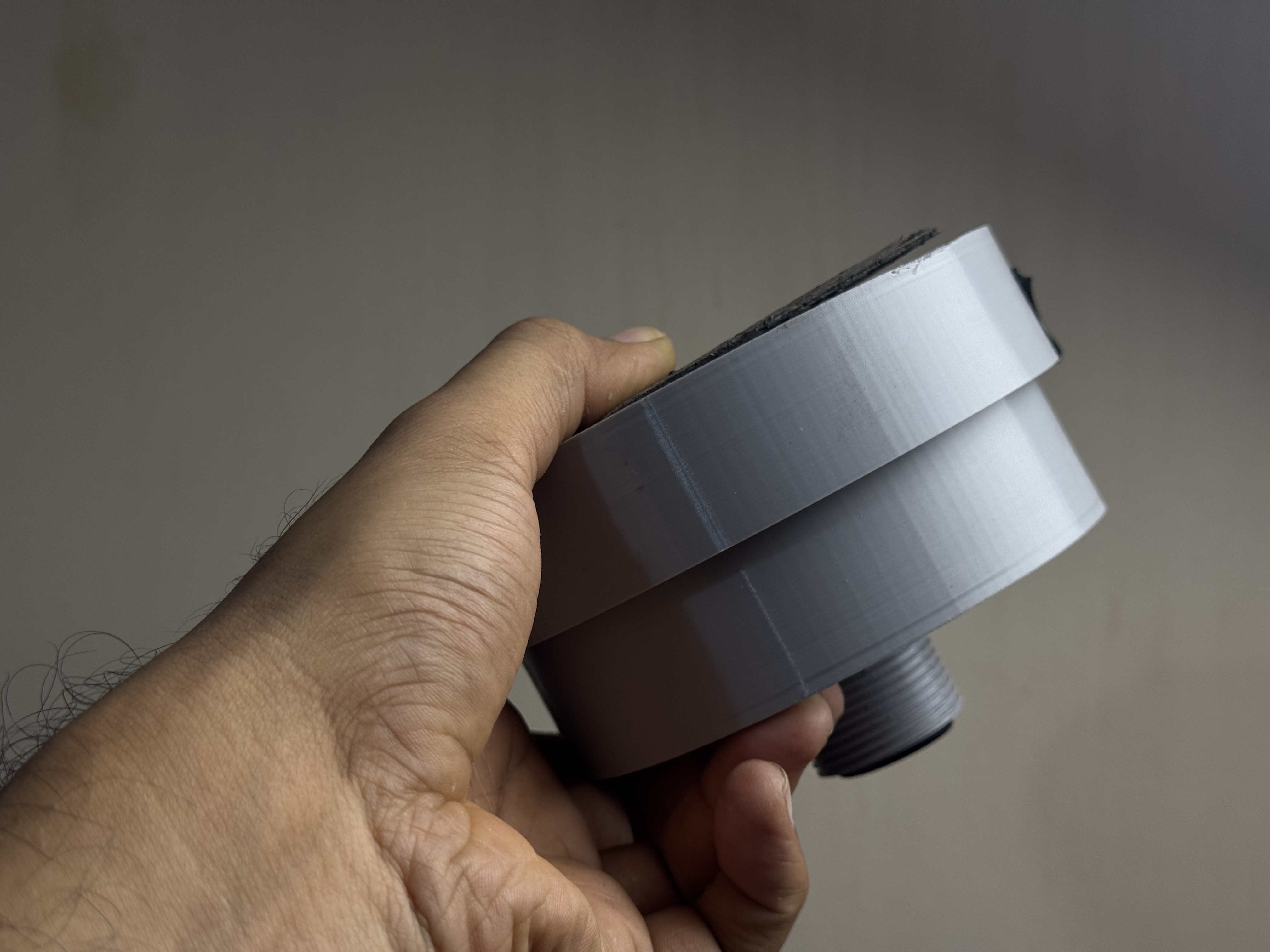
Closed assembly side profile — gasket compressed, ready to mount:
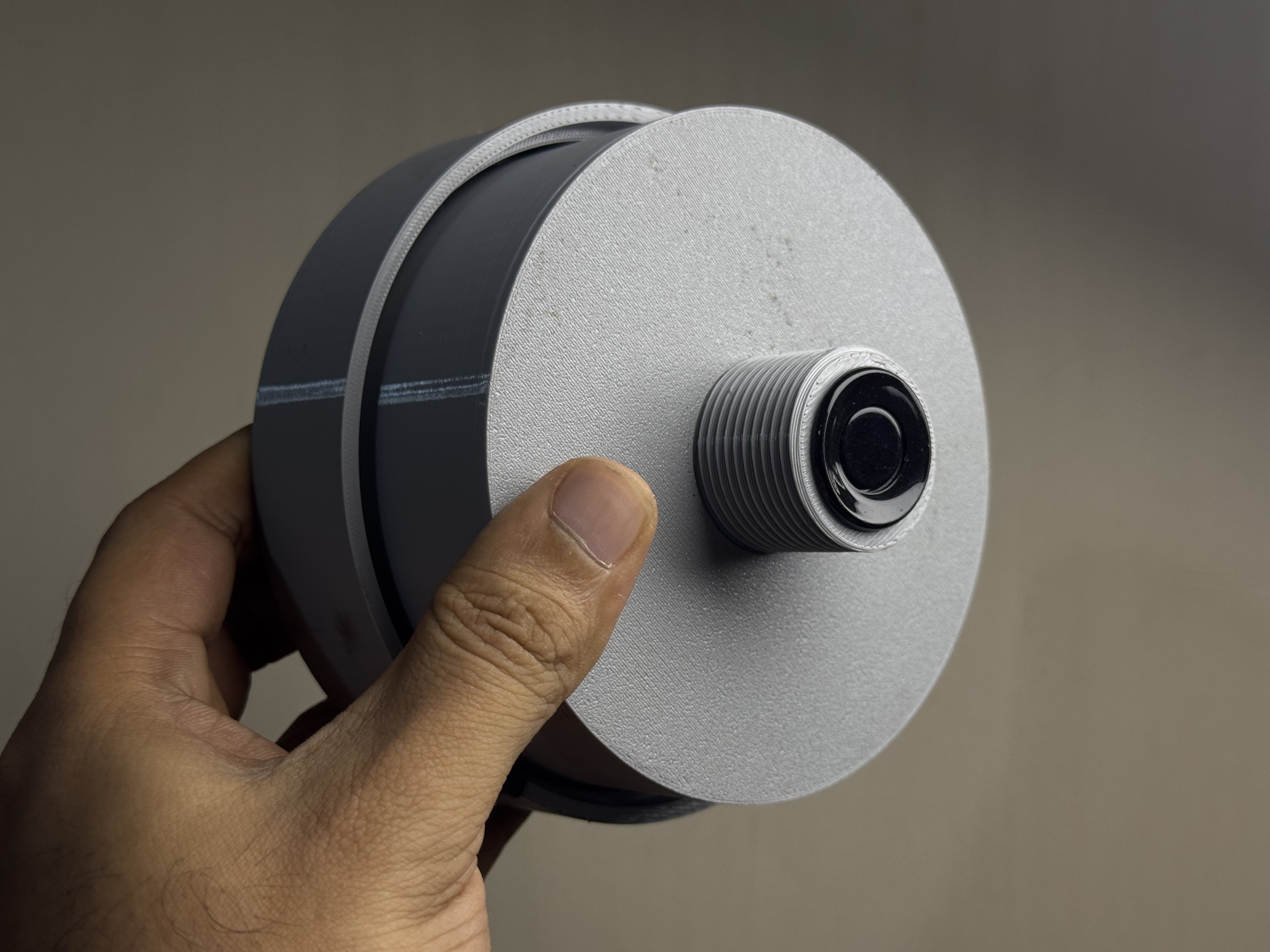
The BSP-threaded sensor mount installed in a test tank lid:
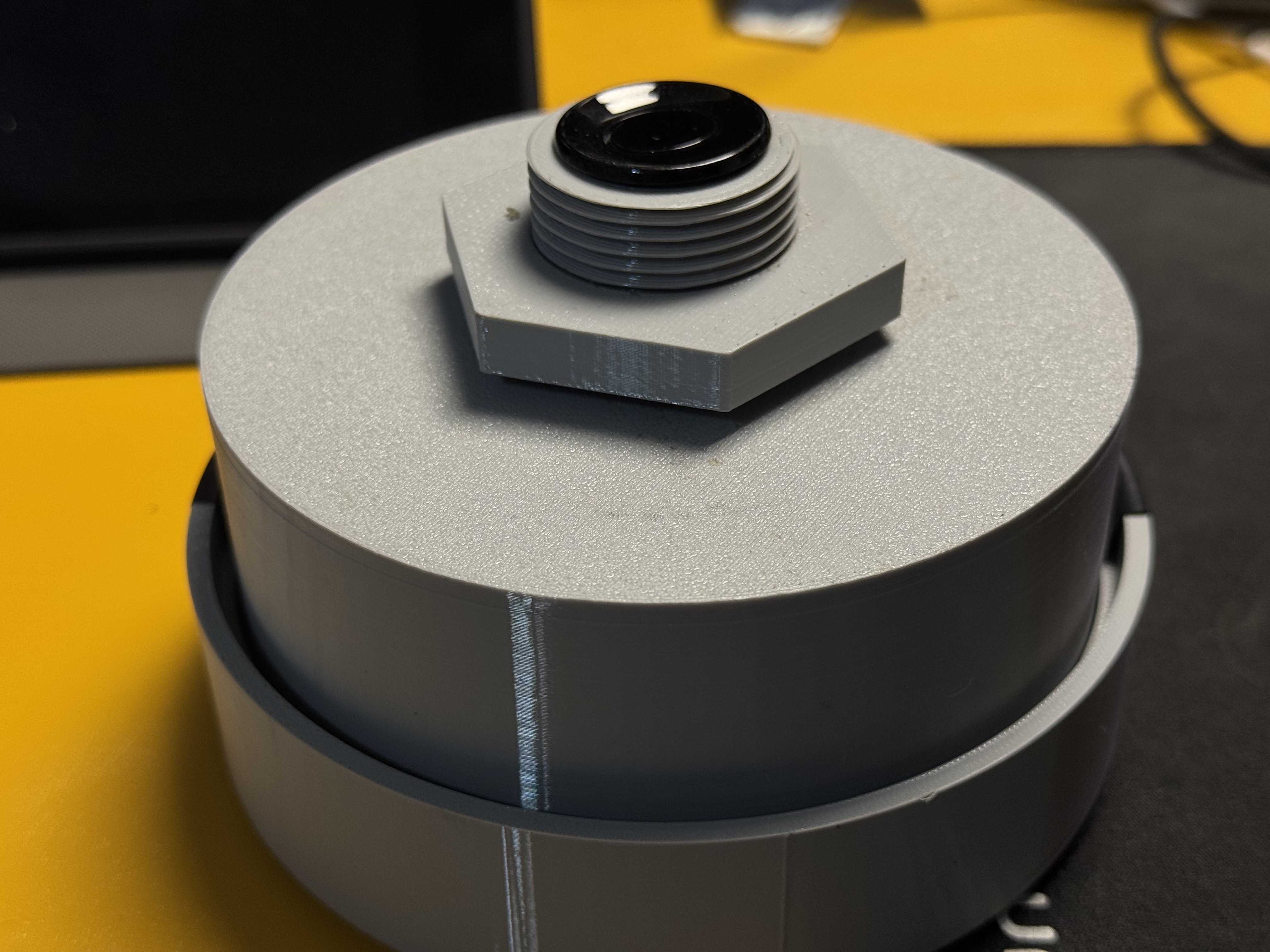
Close-up of the sensor-screw boss + the locking nut from inside the tank:
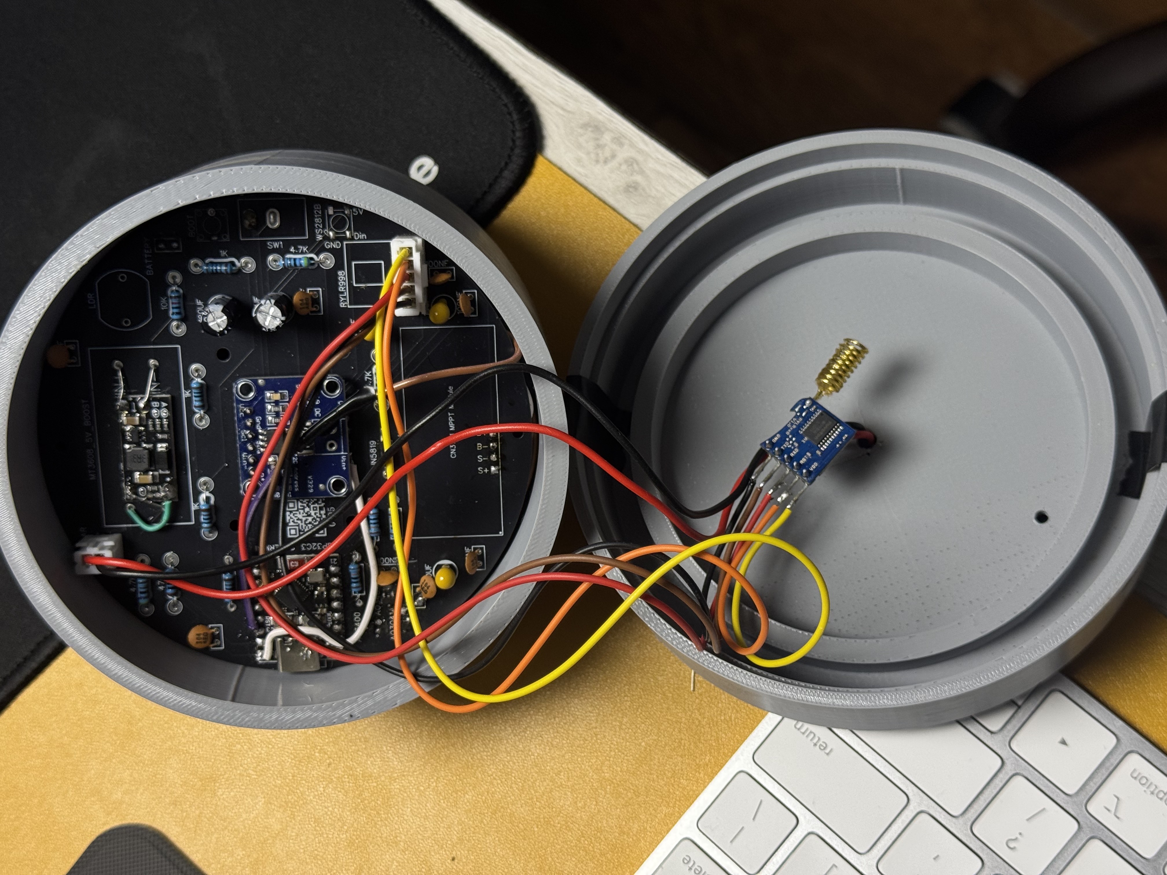
Opened unit showing internal layout + the SMA antenna routing (optional external antenna variant):
Almost every first build hits one of these:
- No 3.3 V at the boost output → MT3608 trim-pot. Adjust with a tiny screwdriver while measuring with a meter.
-
RYLR998 doesn't
+OK→ reversed UART. Try swapping. - Sensor reads zero → ECHO divider wrong polarity, or sensor is in UART mode (R19/R27 solder pads). See Troubleshooting.
- 18650 reads 0 V → reversed cell. The inline Schottky saves the board; reseat the cell.
-
OLED is blank → I²C address wrong (
0x3Dvs0x3C), or SDA/SCL crossed.
For anything else, open an issue with a photo of the board and the idf.py monitor log.