Power Saving
The transmitter is the hard part of TankSync's power story. It runs outdoors on a small solar panel + one 18650 cell, and has to survive Delhi summer (45 °C ambient bench-tested), monsoon-shaded weeks, and the occasional dead-panel month. Average current draw under default settings is ~1.5 mA — so a single fresh 18650 (3000 mAh) lasts roughly 80 days unaided, indefinitely once the panel kicks in.
This page covers how that's achieved across firmware (deep sleep + adaptive duty cycle) and hardware (MOSFET high-side switching + MPPT solar charging).
The hub doesn't need this discipline. It's USB-powered, always-on, and runs the LoRa radio in continuous receive mode. All the power work below is TX-specific.
flowchart LR
    Wake[Deep-sleep wake<br/>~3 ms] --> Power[Drive 5V gate HIGH<br/>50ms settle]
    Power --> Sample[5x ultrasonic samples<br/>median = level]
    Sample --> Pkt[Build TANK packet<br/>+ INA219 read]
    Pkt --> TX[LoRa TX + wait ACK<br/>up to 3s, 3 retries]
    TX --> Off[Drive 5V gate LOW<br/>all loads off]
    Off --> Sleep[Deep sleep<br/>~10µA for 300s]
    Sleep -.->|wake timer| Wake
Per wake event, the TX is awake for ~250 ms. That includes:
- ESP32-C3 boot from RTC memory (~3 ms — no full flash boot, NVS preserved across deep sleep)
- Power-rail settle (50 ms — JSN-SR04T's analog front-end needs this)
- 5 ultrasonic readings × ~50 ms each (median-filtered, ~10 ms per reading + the 30 ms ECHO wait the AJ-SR04M variants need)
- One LoRa TX + ACK round trip (~200 ms typical, up to 3 s on retry)
Then the chip goes back into deep sleep for SLEEP_INTERVAL_S (default 300 s = 5 min).
| Phase | Current draw | Duration |
|---|---|---|
| Deep sleep (5V rail off via P-FETs) | ~10 µA | ~300 s (~99.92 % of cycle) |
| Wake — sensor settling | ~70 mA | 50 ms |
| Wake — sampling | ~10 mA | ~250 ms (8-9 mA is SR04T sit-idle current) |
| Wake — LoRa TX | ~70 mA peak | ~30 ms |
| Average over a 5-min cycle | ~1.5 mA | continuous |
At 1.5 mA average × 3000 mAh = ~80 days before the 18650 dies. Solar charging adds ~10-30 mAh/day in light/medium sun, way more than the daily ~36 mAh draw. So you get indefinite runtime in any reasonably sunlit installation.
The 8-9 mA SR04T sit-idle current is the dominant standby draw inside a "wake" event. Cutting it requires a hardware-only fix (Q2 P-FET to switch the 5V rail to the sensor itself), documented in the high-side-switching section below.
The ESP32-C3 has its own deep-sleep mode that drops the MCU to ~10 µA. But that doesn't help if the RYLR998 LoRa module, JSN-SR04T sensor, and WS2812B status LED are still drawing current from the same rails. So we physically cut power to those loads via P-FETs whenever the C3 sleeps.
flowchart LR
    GPIO10[ESP32-C3 GPIO10<br/>HIGH = wake, LOW = sleep] --> Q3[Q3 — AO3400<br/>N-FET driver]
    Q3 -->|inverted signal| GateBus[Common P-FET gate node]
    GateBus --> Q1[Q1 — AO3401 P-FET<br/>switches +3.3V to RYLR998]
    GateBus --> Q2[Q2 — AO3401 P-FET<br/>switches +5V to SR04T + LED]
All P-FETs share a common ground (and common gate node). The N-FET driver Q3 lets the C3's 3.3 V GPIO control 5 V P-FETs cleanly.
The C3's GPIO is 3.3 V. A P-FET switching a 5 V rail needs 5 V at the gate when OFF (V_GS = 0 → no conduction) and 0 V at the gate when ON (V_GS = -5 V → full conduction). You can't drive that gate cleanly from a 3.3 V GPIO directly:
- 3.3 V on GPIO + P-FET gate connected directly to 5V load: gate sits at ~3.3 V regardless of MCU state → P-FET is always partially on → wasted current.
- The N-FET trick: GPIO drives an N-FET (Q3) gate. Q3's drain is pulled high by 1 kΩ to the 5V rail. When GPIO is HIGH, Q3 conducts → drain goes to GND → P-FET gates pulled to GND → P-FETs fully ON. When GPIO is LOW, Q3 off → drain floats up to 5V via R3 → P-FET gates at 5V → P-FETs OFF.
The R1 100 kΩ pull-down on Q3's gate is critical: it ensures Q3 stays OFF during reset/sleep/power-up before the firmware drives the pin. Without it, the C3's internal weak pull-up + ESD-diode leakage gives ~0.77 V on the gate — enough to partially conduct → keep the loads on → no sleep savings. That was the symptom I bench-measured before wiring the explicit pull-down in.
GPIO10 was originally listed in the schematic plan to gate the MT3608 boost converter's EN pin — that route never made it onto the PCB. GPIO10 IS routed to R3 → Q3 gate, which is its actually-used purpose on this board rev. Don't try to reuse GPIO10 for anything else in firmware.
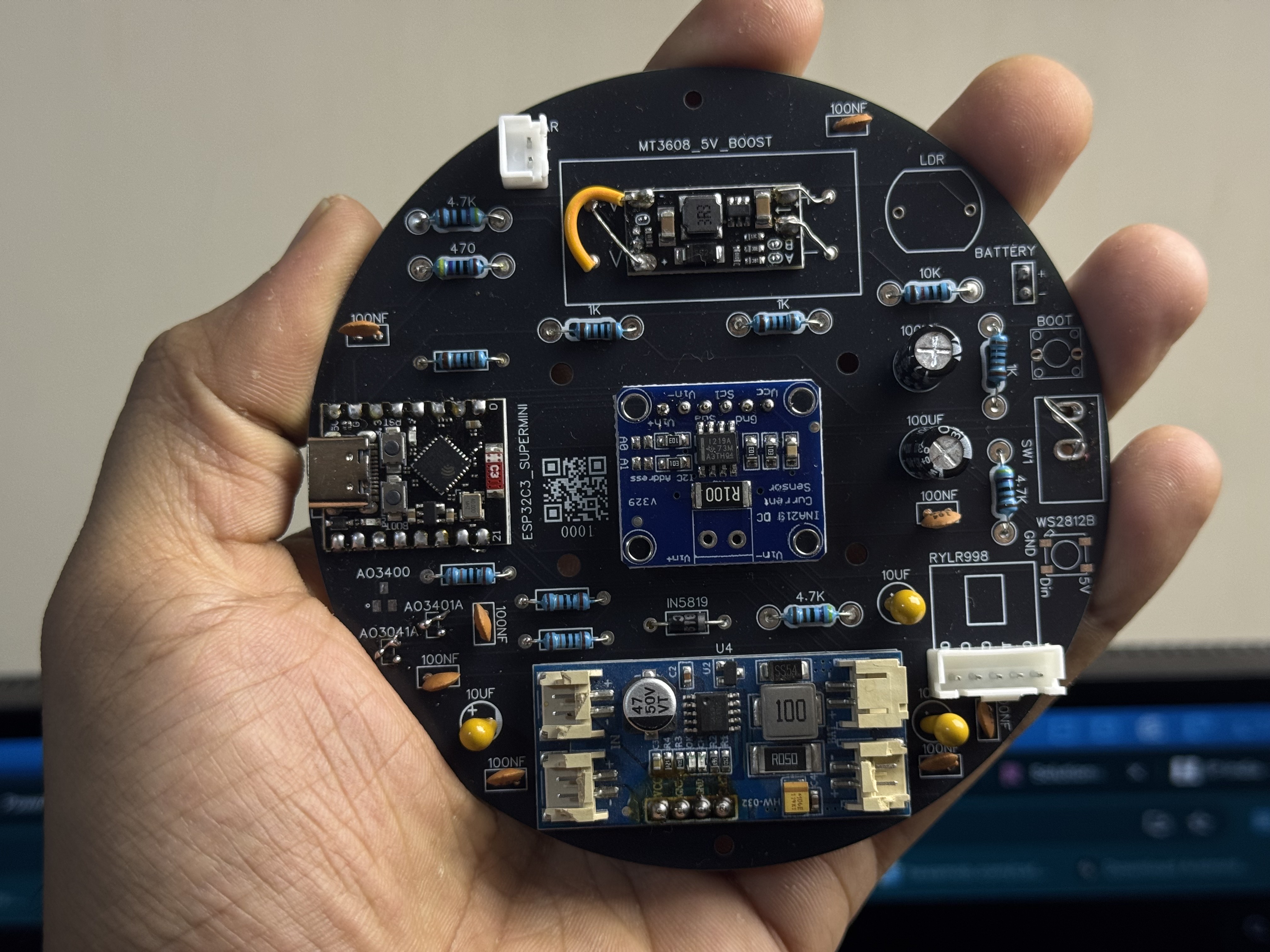
The MOSFETs are visible on the populated PCB top side. Q3 sits near the GPIO10 net trace; Q1 + Q2 sit closer to the RYLR998 + JSN-SR04T connectors respectively.
Panel input is 5–6 V open-circuit, 1–2 W, wired through a Schottky into the CN3791's IN+ / IN- terminals. The CN3791 does MPPT (Maximum Power Point Tracking) — it adjusts its load on the panel dynamically to extract the most power available. Vmpp typically lands around 4.5 V in good sun.
flowchart LR
    Panel[6V 1-2W solar panel] -->|Schottky D1| MPPT[CN3791 MPPT<br/>tracks Vmpp ~4.5V]
    MPPT -->|BAT+| Cell[18650<br/>Li-ion]
    Cell -->|3.0-4.2V| Boost[MT3608 boost<br/>3.3V regulated]
    Boost --> ESP[ESP32-C3<br/>RYLR998<br/>SR04T 5V]
The inline Schottky on the panel input is non-negotiable. Two bench boards were destroyed by reversed cell insertion before this was added. The Schottky drops ~0.3 V (acceptable) and protects against any polarity mishap downstream.
- Bright sun, full panel: charge current up to ~150 mA (panel rating × MPPT efficiency).
- Shaded / cloudy: 5-30 mA. Still positive — slowly tops up.
- Heavy monsoon week: can drop to <5 mA average. The 18650's buffer carries you through.
- Dead panel / disconnected: the unit runs purely on the 18650. ~80 days at the default 5-min wake interval.
The INA219 reads current_ma as a signed number — positive means discharging, negative means charging. You can see this on the PWA tank-detail page (the "Power telemetry" card shows holding 73% · 3.93V · 70mA · via INA219 for example — that's the live cell state).
The TX firmware adjusts SLEEP_INTERVAL_S based on observed conditions:
| Mode | Wake interval | When |
|---|---|---|
| Normal | 300 s | Steady-state default |
| Fill-track | 60 s | Hub detected an active refill on this tank → wake faster to track the rise |
| Leak-watch | 60 s | Hub detected a faster-than-expected drain → wake faster to confirm/refute |
| Stranded | 600 s | TX hasn't received an ACK from the hub in N tries → hub may be off; wake half-rate to save battery until the hub comes back |
The hub pushes interval changes via the TANK_ACK packet's next_check_in_s field. The TX honors them on next wake. No manual configuration needed.
At 60-s intervals (5× faster than default), average current rises from ~1.5 mA to ~5 mA. An 18650 alone would last ~25 days at that pace. So fill-track + leak-watch trigger only during real events, not as a steady state.
You can override the default interval per-tank via the hub's local web UI: Devices → Edit → sleep_interval. Lower = more responsive, less battery. Higher = vice versa.
If your installation gets less sun than typical:
-
Lower sample count — Devices → Edit →
samples. Default 5. Drop to 3 if your tank doesn't have churn. Saves ~10 % per wake. -
Increase sleep interval — Devices → Edit →
sleep_interval. Default 300 s. Raise to 900 s (15 min) if minute-level granularity isn't needed. Saves ~3×. -
Reduce LoRa TX power — Devices → Edit →
lora_pwr. Default = automatic (full power for first pair, then reduced). If your tank is within 100 m of the hub through ≤ 1 wall, you can run at 1-5 mA without packet loss. - Bigger panel — if you can mount a 5 W panel instead of 1-2 W, the duty cycle becomes irrelevant; you'd be solar-powered indefinitely even at faster wake intervals.
Don't try to disable the INA219 or the WS2812 LED to save power — both are µA-class loads dominated by the 8-9 mA SR04T standby. The MOSFET high-side switch is the only real lever.
- Pin assignments + ECHO divider: Wiring (Transmitter)
- Outdoor electronics rules (cap ratings, gasket types, ASA filament): see the Hardware Build → Printing notes section
- Browser flasher: Browser Flasher
- Power telemetry details in the PWA: PWA Walkthrough → Tank detail