For the NeurotechX competition Fixed Challenge, MINT is building an EEG collection system from scratch, that will accurately and effectively collect scalp potentials and minimise noise. The system will use an Arudino microcontroller to send the data aqcuired to the computer. We will then use a python script to live-plot the fourier transform of the data recieved.
We made our design choices based on availability and affordabiliity such that other teams can recreate our system.
This four channel EEG collection system can be easily set up and used. The scripts can be downloaded from the github repository and can be run with any Python interpreter. The four electrodes should be clipped onto the hair and placed closely against the scalp. Alternatively, gel electrodes can be placed on the forehead. The four electrode signals will be processed through the circuit and received by the Arduino Leo pins A0-A3. The 4 signals will be fourier transformed and displayed on the computer through a python plotting script.
Important: Remember to change the port name to what you see in your Arduino IDE (e.g. "Arduino Leonardo on COM4") and to run the correct Arduino program for whichever script you're using (2Reads for 2Time2FFT.py, 4Reads for 4Time.py and 4FFT.py)
We used CAD to design the case for the electrical components out of 3D-printed ABS and sheet metal, with the goals of minmizing interference between the parts and keeping the assembly as small as possible.
We also designed many different styles of electrodes for the EEG system. Choosing to 3D-print the electrodes and then coat them in conductive silver paint allowed us to fully optimize their geometry for skin contact through hair.
The 4-channel EEG system consists of a notch filter, voltage regulator, and instrumentation amplifier.
INA114 Instrumentation Amplifier Circuit
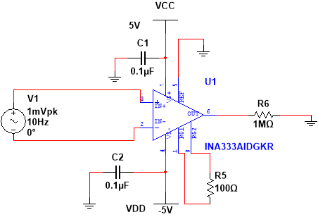
The INA114 circuit acts as a differential amplifier -- it takes an EEG signal from the head and amplifies the difference between it and a reference signal. By implementing four of these circuits, we are able to achieve four EEG channels. Since the Arduino can only read from 0 to 5 volts, the signal acquired through the electrode is amplified by a INA114 precision instrumentation amplifier from microvolts to volts. The INA114 was chosen because it was readily available and affordable.
Shifter Circuit
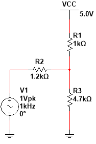
The shifter circuit takes the output of the INA circuit, which is in the range of -5V to +5V, and alters it to make it compatible as an input to the Arduino. The shifter reduces the amplitude of the signal by a half and shifts it to be in the range of 0V to +5V, as required by the Arduino.
Notch Filter
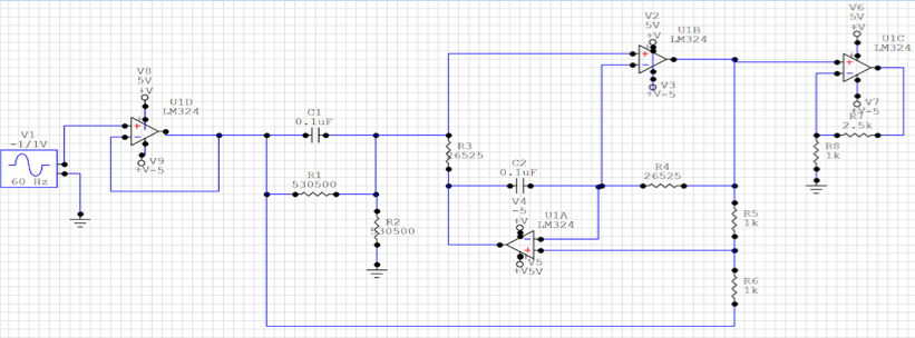
The notch filter then filters out 60Hz noise that arises from power line interference using the LM324 quadruple operational amplifier. Lastly, the 9V battery connects to a voltage regulator to power the entire circuit.
A limitation of Mentha's electrical system is the amount of space available within the mechanical chassis, as we wanted to keep the device small and portable. We had to design our circuits wisely to have efficient use of the available space. In the future we would implement our design on a PCB to optimize layout and increase reliability.
We are using python to collect data from an Arduino and plotting the fourier transform of the the EEG signal in realtime. This allows us to see the peaks in amplitude of the different frequencies of brain signals.
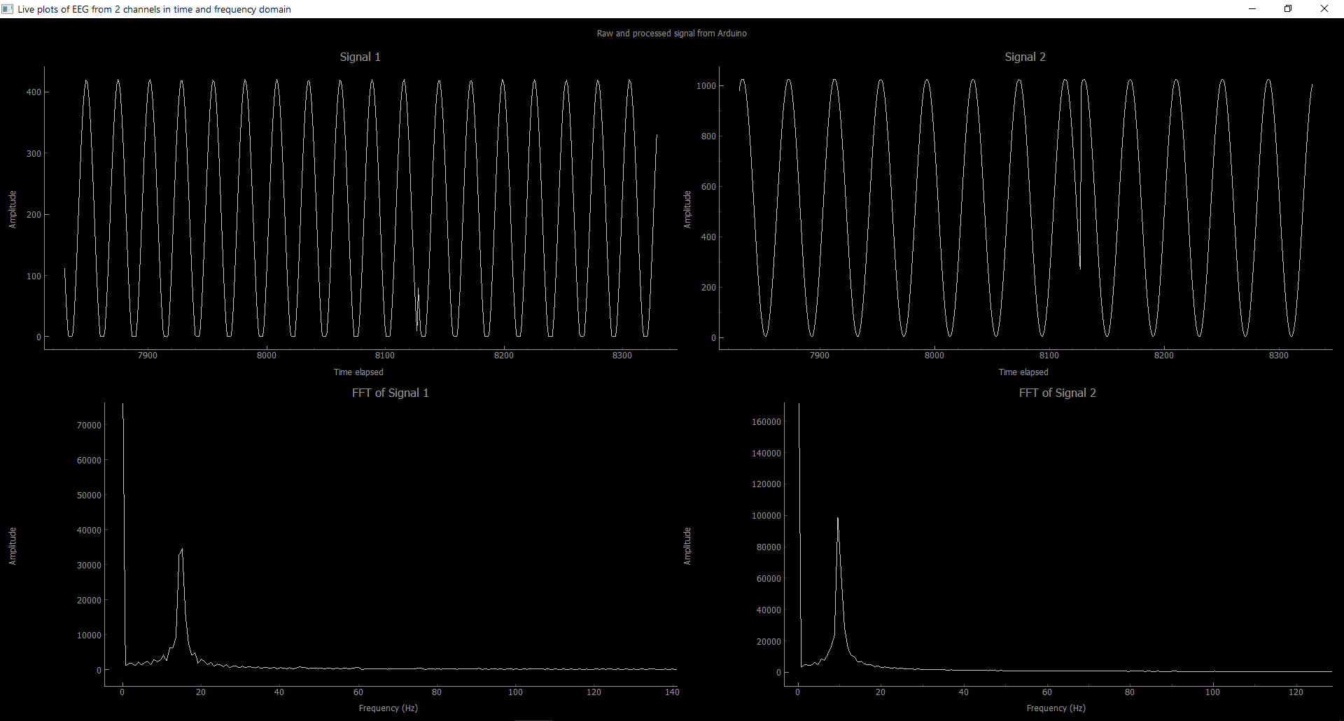
We chose to use pyqtgraph instead of matplotlib to improve the speed of live plotting. We originally prototyped with Matlab, but found that Python provided a better GUI and realtime plotting. As seen in the above figure, the top two graphs depict the original sine wave and the bottom two graphs depict the transformed graph. The script can be easily changed to display 4 FFT plots from 4 channels.
Some challenges we had in designing this script was sending the signals through the serial port and making sure python was able to designate the right label to each signal. For example, when a signal from a single channel was missed such as A1, the remaining signals would shift and the previous A2 would become A1. This was solved by sending all four signals in a string from the Arduino and then parsing in Python accordingly.
The limitations of the software application include the number of channels that acquire data and the delay in the real-time plotting.
To increase the number of channels, we could use more of the pins available on the Arduino. This can be easily added into the python script, albeit we are limited to the number of pins on the Arduino or microcontroller we are using. In the future, we could add more interative components to our system, such as a GUI that allows the user to start and stop data acquisition. Another improvement would include the ability to save data and retrieve previous data. These extra features could also be implemented through a phone app.
Below is the rough breakdown of costs, for those who want to replicate this design:
INA114 x4 = $16
LM7805 x2 = $4
Standard resistors/capacitors = ~$2
LM324 x4 = $2
Sheet aluminium (4 sq. ft. estimate) = $30
Protoype boards x2 = $14
Wires (as needed) = $10
3D Printing Filament (30g @ $0.02/g) = $0.6
Nuts and Bolts = $20
TOTAL $98.6 return
Mentha was created by the (Medical Innovation in NeuroTechnology (MINT) team of undergraduate students, part of the group Biomedical Engineering Student Team at the University of British Columbia in Vancouver, Canada.
Mentha was submitted as a project for the Fixed Challenge category of the NeuroTechX 2018 Student Club competition.