The 11th part in a series of beginner tutorials on integrating physical devices with the IOTA protocol.

This is the 11th part in a series of beginner tutorials where we explore integrating physical devices with the IOTA protocol. Its been i while since i published the last tutorial in this series as I have had to make some other priorities. This will change over the next coming months as I now have received donations from the IOTA development fund that will allow me to continue making these tutorials.
While on the topic, I would like to express my honor and thanks to everyone who have donated to the IOTA development fund. In a space where most actions are fueled by short sighted speculation and greed, the IOTA development fund is truly a unique construct that separate IOTA from other projects.
I was thinking we could start off with a smaller project that has more of a “fun” factor than an actual practical use-case. Beside being a cool and fun project to make, this tutorial is still important as it will give you an introduction to a useful feature of the IOTA tangle, namely the Zero Message Que, or ZMQ for short.
The primary goal of this tutorial is to use an LED cube to visualize the transaction throughput if the IOTA tangle.
As mentioned in the previous section, finding a practical use-case for this particular tutorial might be far fetched. However, learning more about ZMQ and ZMQ streams is always useful as it can be applied to many other real life use cases. One example is the popular tanglemonitor.com
For the sake of relating this tutorial to the other tutorials in this series. I guess you could imagine the hotel owner placing an LED cube in the reception of his hotel as an interesting visual ornament. At the same time, the cube would have a practical function in terms of visualizing the current health and transaction throughput of the IOTA tangle.
Note! In this tutorial we will be monitoring all transactions that are being propagated through to the IOTA network. For monitoring the health of the tangle, it might be more appropriate to focus on confirmed transactions only. This is totally up to you as the ZMQ stream provides both.
ZMQ or ZMQ streams are events or messages being published by an IOTA IRI node if activated. Using a ZMQ listener you could monitor these events and perform actions based on when the event happens, the type of event etc.
In our project we will be monitoring the ZMQ stream for new transactions being attached to the tangle, flashing a random LED on our LED cube whenever this particular event happens.
See here to learn more about the different ZMQ messages being published by the IRI node and the structure of the event message.
Note! Notice that there is a config setting (ZMQ_ENABLED) on the IRI node that defines if ZMQ messages are being published by the node. The ZMQ_ENABLED setting is by default set to False and must be changed to True for the node to start publishing ZMQ messages. Here you can also set the port that the ZMQ messages will be published on. Also notice that most public IRI nodes does not have ZMQ enabled. In case you don’t run your own IOTA node, you could ask the IOTA community on the fullnode Discord channel for a public node that has ZMQ enabled. Or, you could use the following devnet node currently being hosted by the IOTA foundation: tcp://zmq.devnet.iota.org This node is publishing ZMQ messages on port 5556

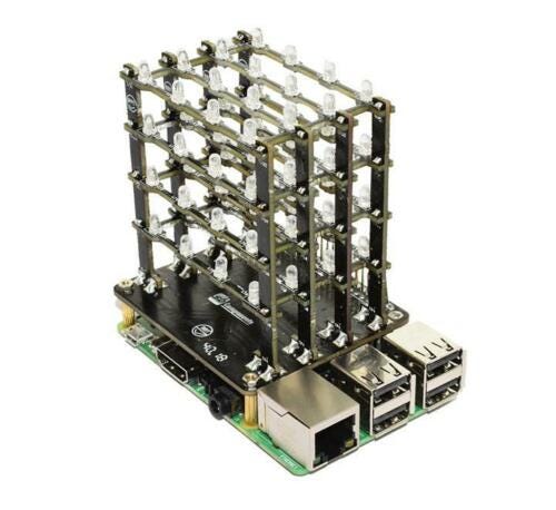
A LED cube is basically a three dimensional matrix (structure) of Light Emitting Diodes (or LED’s for short) wired together using power conducting wires. Using a micro-controller such as the Arduino or Raspberry PI you can make a program that turns on and off the individual LED’s at will, making all kind of interesting light patterns. There are literally hundreds of tutorials out there on how to build your own LED cube if you have have the desire to do so. You can also get complete kits with all the components required to build the cube, including detailed instructions on how to build it. All you need is a soldering iron and a lot of time and patience.
In case you want to go all in on building and programming your own LED cube, you should check out this video for inspiration.
As I personally nether have the time or patience for building my own LED cube from scratch,I decided to get one off ebay for about 25 USD.
The PiCube is kickstarter project that makes a pre-built LED cube that can be mounted directly on top of the Raspberry PI without any wiring or soldering. There is also a github page for the PiCube project where you can get documentation and example code.
Before we start writing our Python code for this project we need to make sure we have all the required software and libraries installed on our Raspberry PI. For this tutorial, the only additional library required (besides the PyOTA library) is the PyZMQ library. To learn more about the PyZMQ library and how to install it, see the following link: https://zeromq.org/languages/python/
The Python code for this project is pretty straight forward so I will not go into details except saying a few words about how to address the individual LED’s in the cube. In my example, I’m simply selecting a random LED to flash for each new IOTA transaction being attached to the tangle. In your version of the project you might want to flash the LED’s in a particular order, if so, you need to know how to address the individual LED’s in the cube.
The basic concept behind a LED cube is that you have the LED’s connected in isolated circuits represented by vertical and horizontal layers. With respect to the PiCube, the LED’s are connected in 16 isolated vertical layers together with 4 individual horizontal layers, making up a total of 64 LED’s. To turn on/off a particular LED in the cube you simply power on/off both the vertical and horizontal layer where the layers meet (and the LED is located). As each individual layer is connected to a particular GPIO pin on the PI, I can now use the PI’s GPOI.output() function to power on/off the individual LED’s
After some testing I found that the LED’s on the PiCube was connected to the PI’s GPIO pin’s according to the following figure.

And here is the Python code for the project.
# Import some standard Python libraries
import time
import random

# Import the Raspberry PI GPIO library
import RPi.GPIO as GPIO

# Import the PyZMQ library
import zmq

# Define some ZMQ objects
context = zmq.Context()
socket = context.socket(zmq.SUB)

# Subscribe to all new and confirmed transaction events
socket.setsockopt(zmq.SUBSCRIBE, b'tx')
socket.setsockopt(zmq.SUBSCRIBE, b'sn')

# Specify IRI node from where to get the ZMQ stream
# IMPORTANT!! IRI node must have ZMQ enabled
socket.connect('tcp://zmq.devnet.iota.org:5556')

# Prepare GPIO board
GPIO.setmode(GPIO.BOARD)
GPIO.setwarnings(False)

# Define list of vertical LEDCube grids
GRID = [7,11,35,37,12,13,31,33,15,16,23,29,18,19,21,22]

# Define list of horizontal LEDCube layers
LAYER = [40,38,36,32]

# Setup layers
GPIO.setup(32, GPIO.OUT)
GPIO.setup(36, GPIO.OUT)
GPIO.setup(38, GPIO.OUT)
GPIO.setup(40, GPIO.OUT)

# Setup individual LED's
GPIO.setup(7, GPIO.OUT)
GPIO.setup(11, GPIO.OUT)
GPIO.setup(37, GPIO.OUT)
GPIO.setup(35, GPIO.OUT)
GPIO.setup(13, GPIO.OUT)
GPIO.setup(12, GPIO.OUT)
GPIO.setup(33, GPIO.OUT)
GPIO.setup(31, GPIO.OUT)
GPIO.setup(16, GPIO.OUT)
GPIO.setup(15, GPIO.OUT)
GPIO.setup(29, GPIO.OUT)
GPIO.setup(23, GPIO.OUT)
GPIO.setup(19, GPIO.OUT)
GPIO.setup(18, GPIO.OUT)
GPIO.setup(22, GPIO.OUT)
GPIO.setup(21, GPIO.OUT)

# Function to flash a random LED
def flash_led():

    # Get random LED
    layer_led = random.choice(LAYER)
    grid_led = random.choice(GRID)

    # Turn on LED
    GPIO.output(layer_led,True)
    GPIO.output(grid_led,True)

    # Keep LED on for 0.05 seconds
    time.sleep(0.05)

    # Turn off LED
    GPIO.output(layer_led,False)
    GPIO.output(grid_led,False)


# Funtion to reset all grid LED's
def reset(x):
        for i in range(0,16):
            GPIO.output(GRID[i],False)

# Funtion to reset all layer LED's
def resetlayer(x):
    for i in range(0,4):
        GPIO.output(LAYER[i],False)

# Make sure all LED's are off before we start...
reset(GRID)
resetlayer(LAYER)

try:
    while(True):

        # Get ZMQ event
        topic, data = socket.recv().decode().split(' ', 1)

        # If ZMQ event is new transaction
        if topic == 'tx':
            tx_hash, address, value, obs_tag, ts, index, lastindex, \
            bundle_hash, trunk_hash, branch_hash, received_ts, tag = data.split(' ')

            # Print transaction data to terminal
            print('NEW TRANSACTION:\n\nAddress: %s\nTransaction hash: %s\nValue: %di \nTag: %s\n' % (address, tx_hash, int(value), tag))

            # Flash random LEDCube LED
            flash_led()


except KeyboardInterrupt:
    GPIO.cleanup()
The source code for this python script can be downloaded from here
To run the the project, you first need to save the scrip from the previous section as text files on your computer.
Notice that Python program files uses the .py extension, so save the files as zmq_cube.py on your Raspberry PI
To execute the scripts, simply start a new terminal window, navigate to the folder where you saved the script and type:
python zmq_cube.py
You should now see random LED’s on your PiCube start flashing, where each flash represents a new transaction being added to the IOTA tangle.
In your terminal window you should also see some basic data for the individual transactions, such as the address, transaction hash, value and tag.
If you like this tutorial and want me to continue making others, feel free to make a small donation to the IOTA address shown below.

NYZBHOVSMDWWABXSACAJTTWJOQRPVVAWLBSFQVSJSWWBJJLLSQKNZFC9XCRPQSVFQZPBJCJRANNPVMMEZQJRQSVVGZ