Test Setup
My main test board is UNO WiFi, but for the GENERIC_ESP8266 test I used some strange components.

I use an ESP-12 module on 5 V adapter board with ESP-01 header. But the GPIO pins were not connected. I patched GPIO0 in, to be able to put the ESP in bootloader mode. On the picture you see a paperclip jumper connecting GPIO0 to ground.

For the MCU OTA upload test I connected the ESP to Seeeduino Lotus. It is an Uno pinout compatible board with SMD ATmega 328p. It is full of Grove connectors. One of them is UART. It is much simpler to connect it with Grove connector then to headers. And you see the GPIO0 of the ESP connected to Uno reset pin on the ISCP header (I had no male/male cable).
For the SoftwareSerial test the ESP was connected to D6+D7 Grove connector.
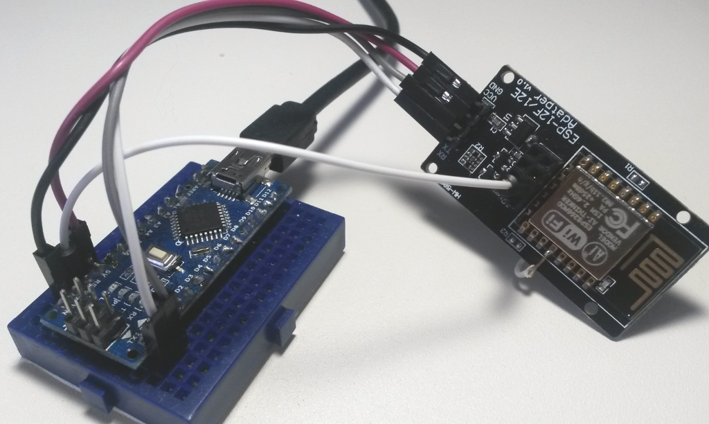
Setup with Nano:
MKR Zero with esp-01S:

The MKR Zero is a 3.3 V board. The esp-01S doesn't require EN/CH-PD and io0 wiring like the esp-01. I made a hole in the breadboard for the 4 middle pins of the esp-01S.
To test the SPI build of WiFi Link, I bought a Wemos D1 mini clone, because it breaks out the esp8266 pins including the HSPI pins. I connected it with a Nano clone with level conversion. I did not solder the header of ICSP on Nano, so I connected the SPI pins to D labeled equivalents.

The SPI connection takes a lot of pins, but it is the same with Ethernet and WiFi shield.

SPI pins are on the ICSP header of UNO/Mega/Nano (digital pins 11, 12, 13). Pin 10 is needed as SPI SLAVESELECT and pin 7 is used by WiFi Link as SLAVEREADY signal from the esp8266 GPIO pin 5 (D1). For ATmega OTA upload GPIO pin 4 (D2) of esp8266 is used to reset the ATmega and Atmega pin 4 is connected to reset esp8266 from Atmega sketch.
WiFiLik SPI with MKR Zero:
