In this assignment, I made a temperature sensor read the current temperature in Fahrenheit and Celsius, and output those temperatures onto an LCD. The LCD also displays an indicator of if the temperature is within reasonable room temperature, too warm, or too cold.
import board
import analogio
import time
from lcd.lcd import LCD
from lcd.i2c_pcf8574_interface import I2CPCF8574Interface


TMP36_PIN = board.A0  # Analog input connected to TMP36 output.

i2c = board.I2C()
lcd = LCD(I2CPCF8574Interface(i2c, 0x3f), num_rows=2, num_cols=16)


# Function to simplify the math of reading the temperature.
def tmp36_temperature_C(analogin):
    millivolts = analogin.value * (analogin.reference_voltage * 1000 / 65535)
    return (millivolts - 500) / 10


# Create TMP36 analog input.
tmp36 = analogio.AnalogIn(TMP36_PIN)

# Loop forever.
while True:
    # Read the temperature in Celsius.
    temp_C = tmp36_temperature_C(tmp36)
    temp_C = round(temp_C, 1)
    # Convert to Fahrenheit.
    temp_F = (temp_C * 9/5) + 32
    temp_F = round(temp_F, 1)
    # Print out the value and delay a second before looping again.
    lcd.print("{}C {}F".format(temp_C, temp_F))
    lcd.set_cursor_pos(1,0)
    if temp_F > 78:
        lcd.print("TOO HOT!        ")
    elif temp_F < 70:
        lcd.print("brrrrr TOO COLD ")
    else:
        lcd.print("FEELS GREAT HERE")

    time.sleep(.25)
    lcd.set_cursor_pos(0,0)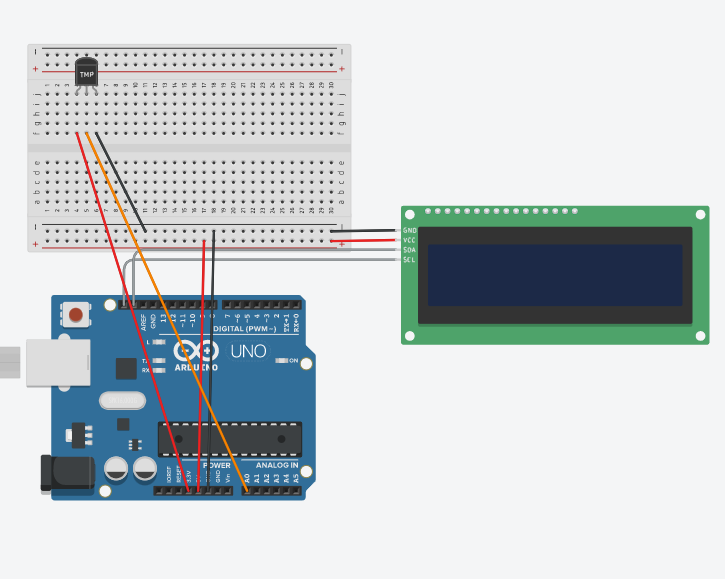
IMG_0.2.MOV
This assignment wasn't too challenging, and I didn't run into any technical difficulties. I was able to find the basic formulas online to convert the temperature sensor's input into usable numbers, and implementing the code was farily simple. After that, it was just a matter of setting up the LCD and formatting the output properly.
In this assignment, I made used a rotary encoder to navigate a menu of 3 stoplight colors, and then turn the selected color on when the button is pressed.
Code is mostly the work of Graham. I made changes to fit my lcd, and so that the lcd messages would display more clearly.
import time
import rotaryio
import board
from lcd.lcd import LCD
from lcd.i2c_pcf8574_interface import I2CPCF8574Interface
from digitalio import DigitalInOut, Direction, Pull

encoder = rotaryio.IncrementalEncoder(board.D3, board.D2)
last_position = 0
btn = DigitalInOut(board.D4)
btn.direction = Direction.INPUT
btn.pull = Pull.UP
state = 0
buttonState = 1

i2c = board.I2C()
lcd = LCD(I2CPCF8574Interface(i2c, 0x3f), num_rows=2, num_cols=16)

ledGreen = DigitalInOut(board.D8)
ledYellow = DigitalInOut(board.D9)
ledRed = DigitalInOut(board.D10)
ledGreen.direction = Direction.OUTPUT
ledYellow.direction = Direction.OUTPUT
ledRed.direction = Direction.OUTPUT

while True:
    position = encoder.position
    if position != last_position:
        if position > last_position:
            state = state + 1
        elif position < last_position:
            state = state - 1
        if state > 2:
            state = 2
        if state < 0:
            state = 0
        print(state)
        if state == 0:
            lcd.set_cursor_pos(0, 0)
            lcd.print("GO    ")
        elif state == 1:
            lcd.set_cursor_pos(0, 0)
            lcd.print("CAUTION")
        elif state == 2:
            lcd.set_cursor_pos(0, 0)
            lcd.print("STOP  ")
    if btn.value == 0 and buttonState == 1:
        print("button pressed")
        if state == 0:
                ledGreen.value = True
                ledRed.value = False
                ledYellow.value = False
        elif state == 1:
                ledYellow.value = True
                ledRed.value = False
                ledGreen.value = False
        elif state == 2:
                ledRed.value = True
                ledGreen.value = False
                ledYellow.value = False
        buttonState = 0
    if btn.value == 1:
        time.sleep(.1)
        buttonState = 1
    last_position = position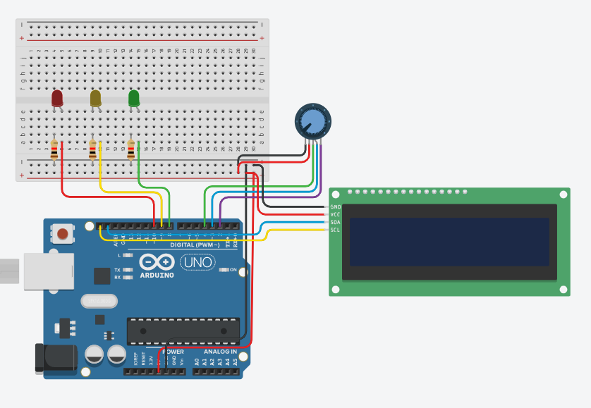
IMG_0.3.MOV
This assignment was a good refresher on leds and buttons with CircuitPython, as well as a good introduction to a new part. The code got a bit jumbled once the button past of the encoder was introduced, but it wasn't too hard to get all of the parts working.
In this assignment, I got a photointerrupter to detect how many times it had been interrupted, and then print that value every 4 seconds.
import time
import digitalio
import board

photoI = digitalio.DigitalInOut(board.D7)
photoI.direction = digitalio.Direction.INPUT
photoI.pull = digitalio.Pull.UP

last_photoI = True
last_update = -4

photoICrosses = -1

while True:
    if time.monotonic()-last_update > 4:
        print(f"The number of interupts is {photoICrosses}")
        last_update = time.monotonic()

    if last_photoI != photoI.value and not photoI.value:
        photoICrosses += 1
    last_photoI = photoI.value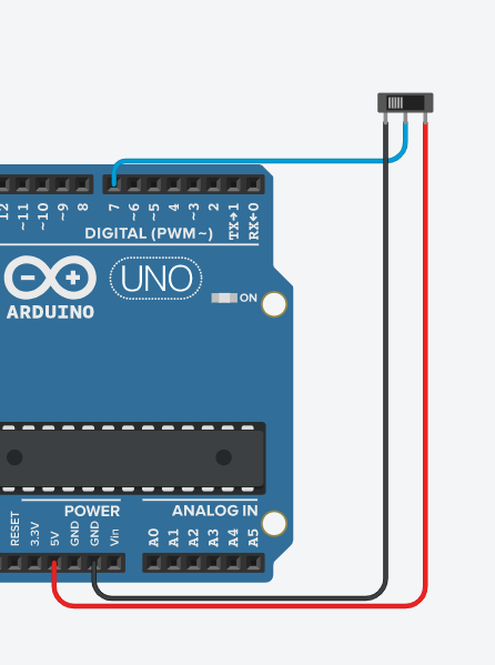
IMG_0.4.MOV
This assignment was pretty basic, and there wasn't really wiring. The code was a bit more interesting, though, and even though it wasn't very long it had some interesting logic to detect full interrupts.