


This project has a specific target of providing a low-cost, open source technological kit to allow scientists, academics, hackers, makers or OSHW fans to hack their way to ultrasound imaging - below 500$ - at home, with no specific equipment required. For complementary sources of information, you can visit:
- the github repo, for the source files, raw data and raw experiment logs;
- the online manual/book for a easily readable and searchable archive of the whole work;
- with list of probes
- and list of experiments
- the hackaday page, where I tried to blog day-to-day experiments in a casual format;
- an article summarizing the experiment on the Journal of Open Hardware - DOI:10.5334/joh.2;
- the slack channel if you want to discuss;
- the Tindie store for the analog processing unit and the unipolar pulser or the motherboard.
- And of course, the ice40 research board, on un0rick.cc and its doc or even its github. It's a bit cheaper, and has better specs.
- Disclaimer #0: This is not a medical ultrasound scanner! It's a development kit that can be used for pedagogical and academic purposes - possible immediate use as a non-destructive testing (NDT) tool, for example in metallurgical crack analysis. As in all electronics, be careful.
- Disclaimer #1: though an engineer, this project is the first of its sort, I never did something related. It's all but a finalized product.
- Disclaimer #2: Ultrasound raises questions. In case you build a scanner, use caution and good sense!
- Disclaimer #3: This project is not part of echopen.
Medical ultrasound is based on the use of high frequency sound to aid in the diagnosis and treatment of patients. Ultrasound frequencies range from 2 MHz to approximately 15 MHz, although even higher frequencies may be used in some situations.
The ultrasound beam originates from mechanical oscillations of numerous crystals in a transducer, which are excited by electrical pulses (piezoelectric effect). The transducer converts one type of energy into another (electrical <--> mechanical/sound).

The ultrasound waves (pulses of sound) are sent from the transducer, propagate through different tissues, and then return to the transducer as reflected echoes when crossing an interface. The returned echoes are converted back into electrical impulses by the transducer crystals and are further processed - mostly to extract the enveloppe of the signal, a process that transforms the electrical signal in an image - in order to form the ultrasound image presented on the screen.
Ultrasound waves are reflected at the surfaces between the tissues of different density, the reflection being proportional to the difference in impedance. If the difference in density is increased, the proportion of reflected sound is increased and the proportion of transmitted sound is proportionately decreased.
If the difference in tissue density is very different, then sound is completely reflected, resulting in total acoustic shadowing. Acoustic shadowing is present behind bones, calculi (stones in kidneys, gallbladder, etc.) and air (intestinal gas). Echoes are not produced on the other hand if there is no difference in a tissue or between tissues. Homogenous fluids like blood, bile, urine, contents of simple cysts, ascites and pleural effusion are seen as echo-free structures.
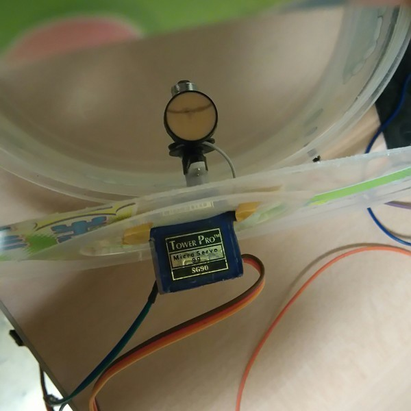
If the process is repeated with the probe sweeping the area to image, one can build a 2D image. In practice, in the setups we'll be discussing, this sweep is done with a transducer coupled to a servo, or using a probe that has an built-in motor to create the sweep.

A critical component of this system is the ultrasound transducer. A typical ultrasound imaging system uses a wide variety of transducers optimized for specific diagnostic applications, but in our case, we'll limit the costs.
High-Voltage Transmitters (see the module)
A digital transmit beamformer typically generates the necessary digital transmit signals with the proper timing and phase to produce a focused transmit signal. High-voltage pulsers quickly switch the transducer element to the appropriate programmable high-voltage supplies to generate the transmit waveform. To generate a simple bipolar transmit waveform, a transmit pulser alternately connects the element to a positive and negative transmit supply voltage controlled by the digital beamformer. More complex realizations allow connections to multiple supplies and ground in order to generate more complex multilevel waveforms with better characteristics.
TGC + LNA = Variable-Gain Amplifier (VGA) (see the module)
The LNA in the receiver must have excellent noise performance and sufficient gain. In a properly designed receiver the LNA will generally determine the noise performance of the full receiver.
The VGA, sometimes called a time gain control (TGC) amplifier, provides the receiver with sufficient dynamic range over the full receive cycle. Ultrasound signals propagate in the body at approximately 1540 meters per second and attenuate at a rate of about 1.4dB/cm-MHz roundtrip. Immediately after an acoustic transmit pulse, the received "echo" signal at the LNA's input can be as large as 0.5VP-P. This signal quickly decays to the thermal noise floor of the transducer element. The dynamic range required to receive this signal is approximately 100dB to 110dB, and is well beyond the range of a realistic ADC. As a result, a VGA is used to map this signal into the ADC. A VGA with approximately 30dB to 40dB of gain is necessary to map the received signal into a typical 12-bit ADC used in this application. The gain is ramped as a function of time (i.e., "time gain control") to accomplish this dynamic range mapping.
Anti-Alias Filter (AAF) and ADC (see the module)
The AAF in the receive chain keeps high-frequency noise and extraneous signals that are beyond the normal maximum imaging frequencies from being aliased back to baseband by the ADC. Many times an adjustable AAF is provided in the design. To avoid aliasing and to preserve the time-domain response of the signal, the filter itself needs to attenuate signals beyond the first Nyquist zone. For this reason Butterworth or higher-order Bessel filters are used.
The ADC used in this application is typically a 12-bit device running from 40Msps to 60Msps. This converter provides the necessary instantaneous dynamic range at acceptable cost and power levels. In a properly designed receiver, this ADC should limit the instantaneous SNR of the receiver. As previously mentioned, however, limitations in the poor-performing VGAs many times limit receiver SNR performance
[](@description Short description of the organization of modules)
To produce an image, the modules have to create a high voltage pulse, which excites a transducer. Echoes coming from the body are amplified using a TGC + LNA, which cleans the analog signal, which itself gets digitalized.
The diagram is represented below:

Non destructive testing and imaging ultrasound modalities have been around since the '50s in . More and more ultrasound-based initiative are emerging, mostly focusing on image processing - while hardware has been left behind. Several teams have produced succesful designs for the different possible uses, mostly efforts from research laboratories. Most have been used on commercial US scanners, traditionaly used as experiment platforms, but they are not cheap, and yield very little in terms of data access and control. Others have been developped in labs, but, sadly, very few have been open-sourced. Let's tackle this!
It has also been shown that simple (be it low-power, low-cost and small) can be achieved - and this, even for relatively complex systems, based on 16 to 64 parallel channels front-end processing and software back-end processing (embedded PC or DSP). This makes it a bit more complex for the layman, hobbyist, or non-specialist researcher to use, not to mention the very little information that is accessible.
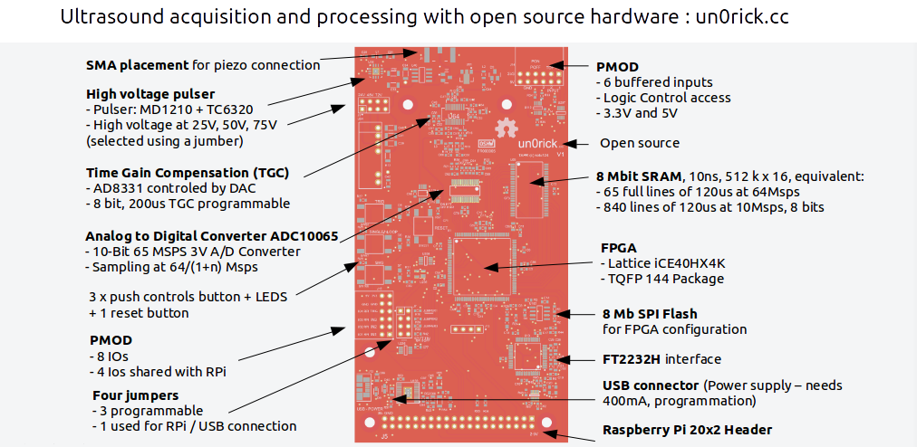
- FPGA: Lattice iCE40HX4K - TQFP 144 Package
- Memory:
- 8 Mbit SRAM, 10ns, 512 k x 16, equivalent:
- 65 full lines of 120us at 64Msps
- 840 lines of 120us at 10Msps, 8 bits
- 8 Mb SPI Flash for FPGA configuration
- Ultrasound processing:
- VGA: AD8331 controled by DAC
- Pulser: MD1210 + TC6320
- ADC: 65Msps ADC10065
- 10 bits of data / sample
- 2 bits of line counters
- 4 bits of IOs (counters, ...)
- Parameters: Settings programable via USB or Raspberry Pi
- Type of acquisition (one line / set of lines)
- Number of lines
- Length of lines acquisitions
- Delay between acquisitions
- Pulse width
- Delay between pulse and beginning of acquisitions
- 200us time-gain-compensation programmable (8 bits, from 0 to Max), every 5us
- Extensibility:
- 2 x Pmod connectors
- SMA plug for transducers
- RPi GPIO
- User Interfaces:
- 2 x PMOD for IOs
- 3 x push button (with software noise debouncing)
- Jumpers for high voltage selection
- Input Voltage:
- 5 V from RPi or USB
- Uses 350mA-450mA at 5V
- Fully Open Source:
- Hardware: github repository
- Software: github repository
- Toolchain: Project IceStorm
- Documentation: gitbook
- Operating Voltage:
- FPGA and logics at at 3.3 V
- High voltage at 25V, 50V, 75V
- Dimensions: @todo!
- Weight: @todo!
| Tool | Murgen | echOmods | unoric |
|---|---|---|---|
| Open Source | Yes | Yes | Yes |
| ADC | 20Msps | 1Msps to 24Msps | 65Msps up to 100Msps |
| Onboard memory | 300 Mb | 10 Mb | 20Mb |
| Price of a set | 400$ | 450$ | 400$ |
| Modular | Np | Yes | No |
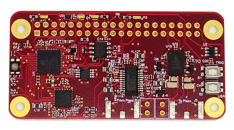
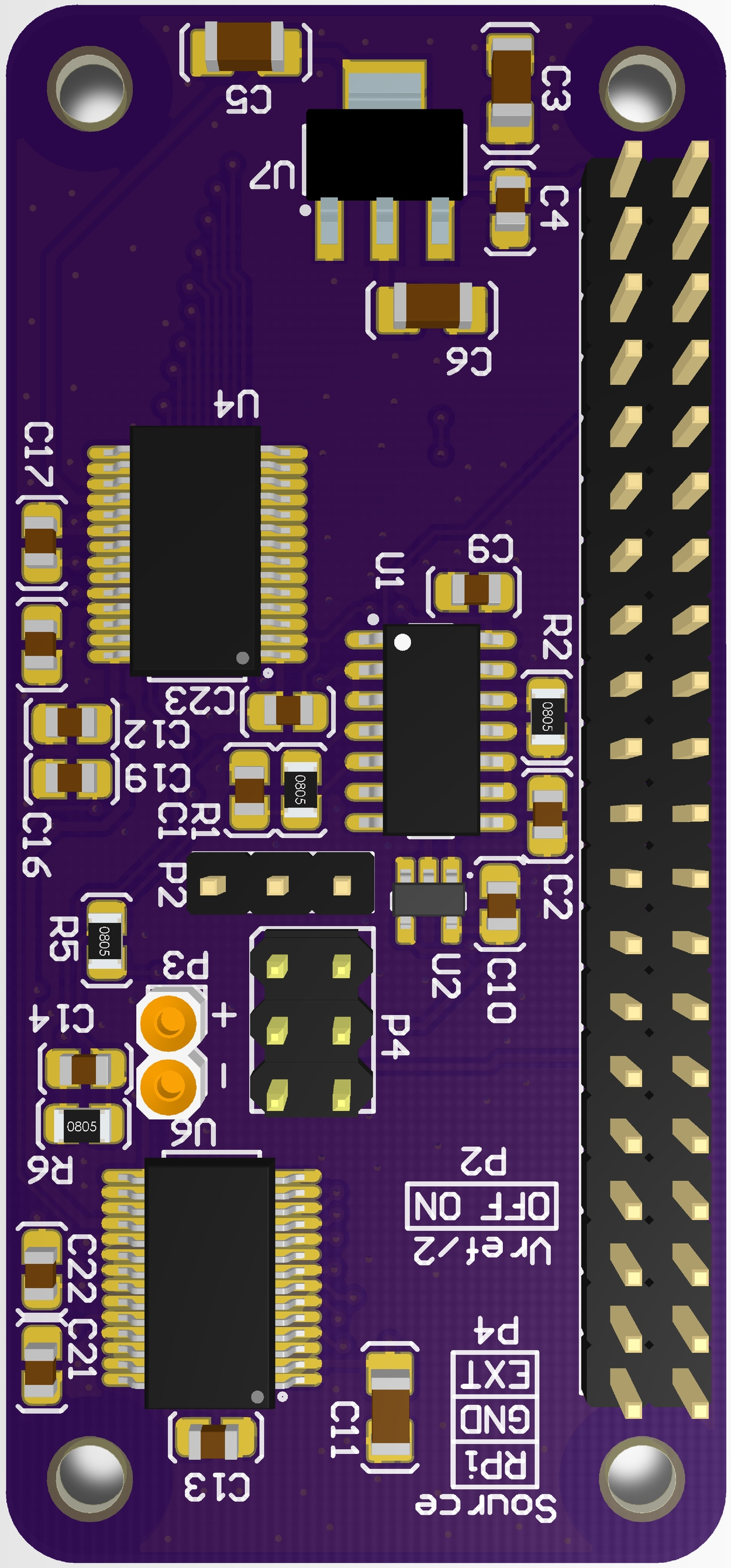
Creating modules to facilitate ultrasound hacking : the principles of the echOmods is to enable a full chain of ultrasound image processing and hardware control.
We have chosen to use a module approach to make sure that each key component inside ultrasound image processing can easily be replaced and compared with another module, while providing logical logic blocks and corresponding interfaces for these modules to communicate. There's a module for high-voltage pulsing, one for the transducer, one for the analog processing, one for data acquisiton, ... and many more!

The modules sit on a breadboard, and communicate through the tracks laying below. The configuration represented below show the Basic dev kit.

and used in a wider context:

| ThumbnailImage | Name | In | Out |
|---|---|---|---|
 |
goblin: The aim of this echOmod is to get the signal coming back from a transducer, and to deliver the signal, analogically processed, with all steps accessible to hackers. |
|
|
 |
wirephantom: Just a phantom for calibrated signals |
|
|
 |
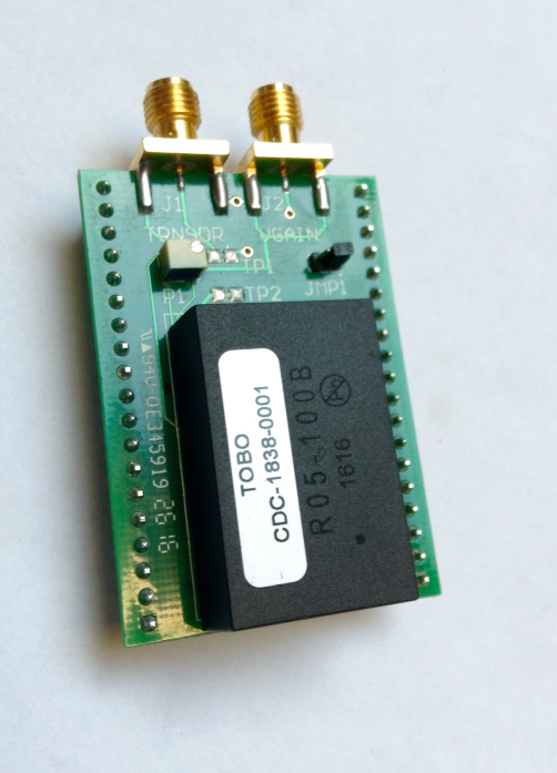
lite.tbo: The aim of this echOmod is to get the HV Pulse done. |
|
|
 |
silent: The aim of this echOmod is to simulate a raw signal that would come from the piezo and analog chain. |
|
|
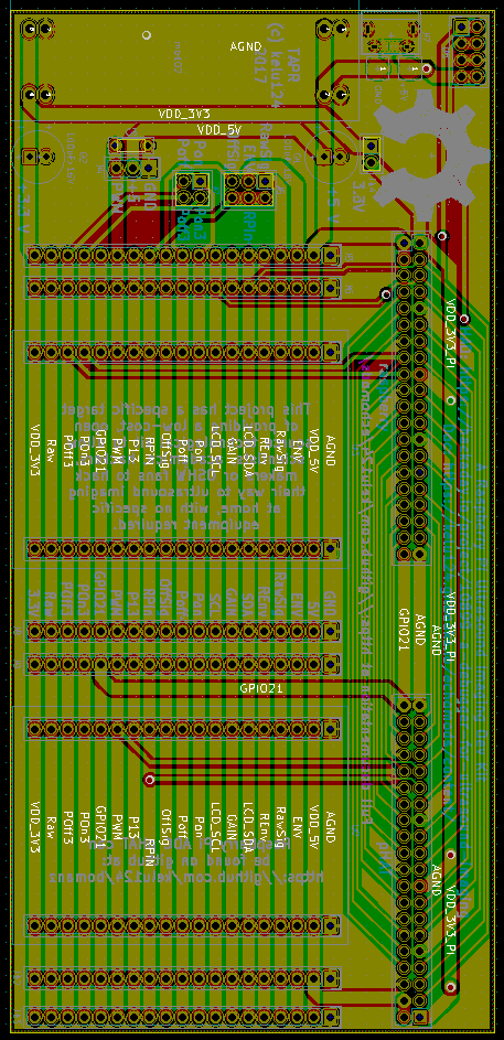 |
doj: Getting a motherboard: that's fitting all the modules in an easy way, with an easy access to all tracks. See this for the Kicad files. | ||
 |
retroATL3: The aim of this echOmod is to get the mechanical movement of the piezos. Salvaged from a former ATL3. |
|
|
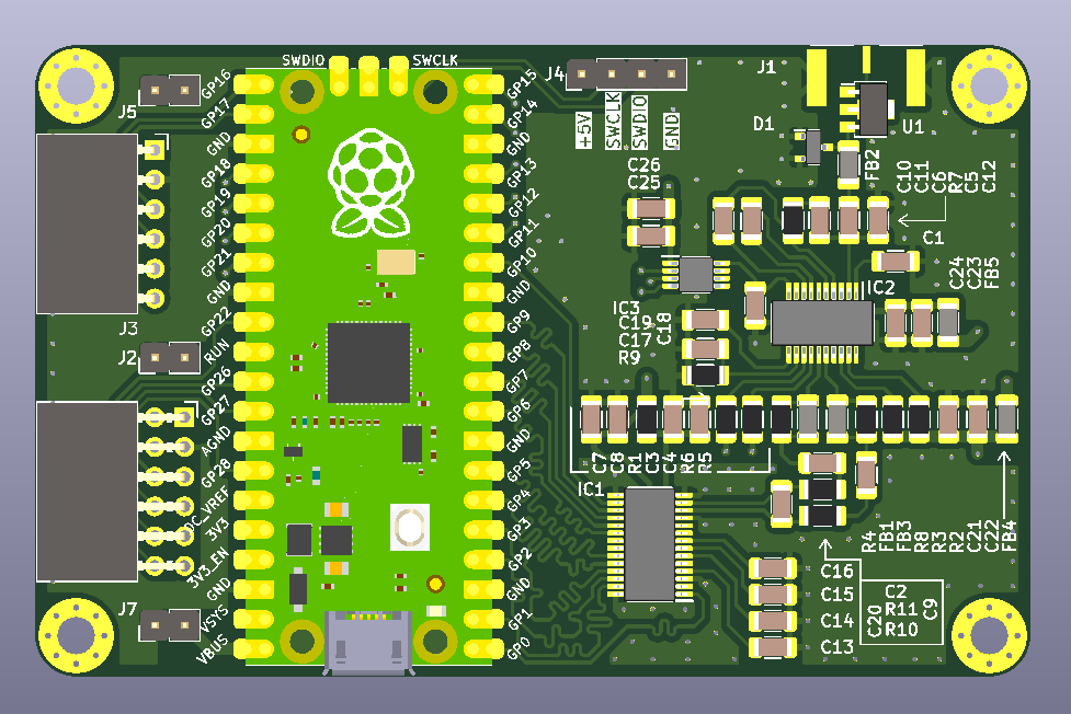 |
pic0: Using a rp2040 to do a full blown pulse echo device. | ||
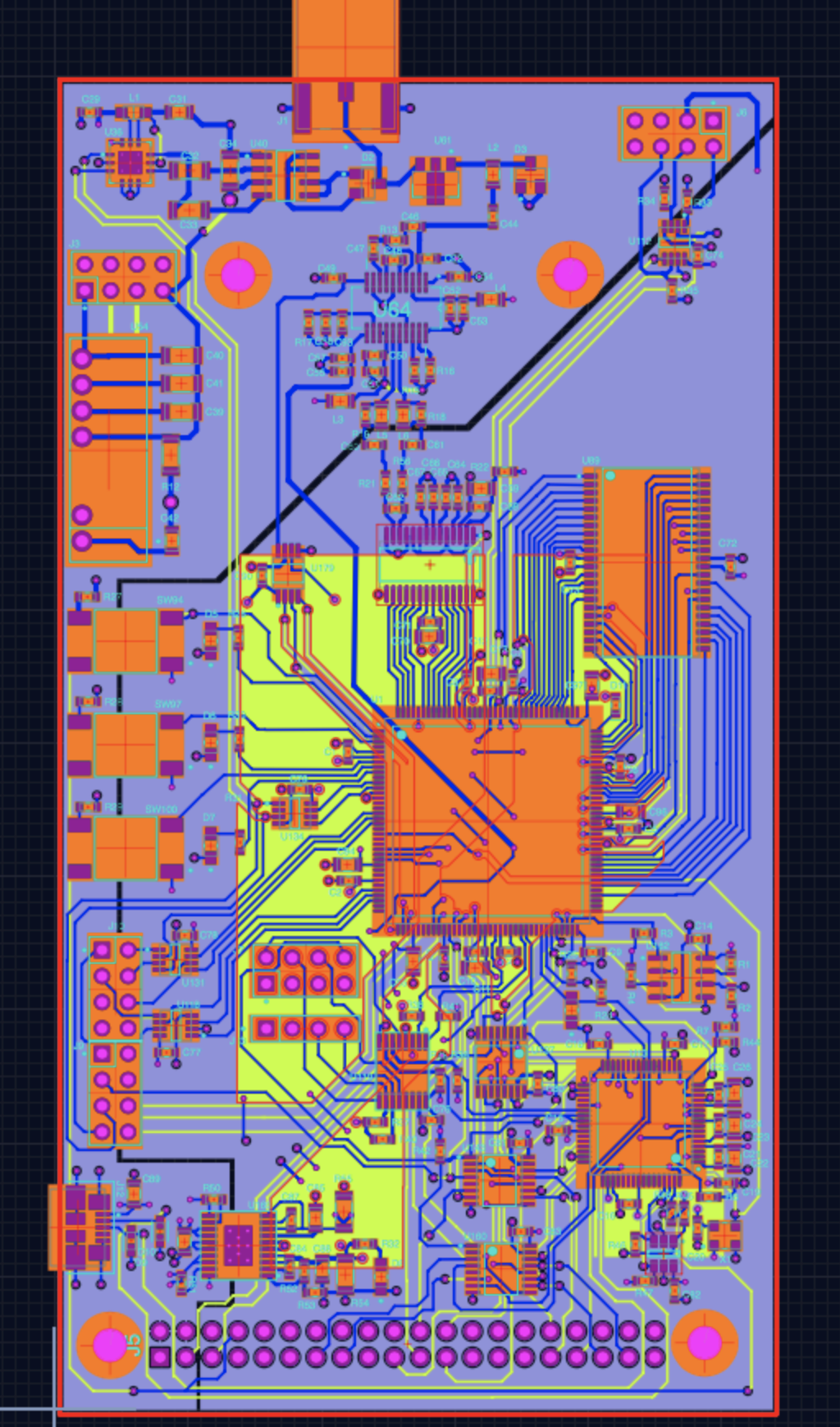 |
matty: The aim is to summarize all modules in a all-inclusive board. Fast ADC, good load of memory, good SNR.. the not-so-DIY module, as it comes already assembled with nothing to do =) | ||
 |
lit3rick: The aim is to summarize all modules in a all-inclusive board. Fast ADC, good load of memory, good SNR.. the not-so-DIY module, as it comes already assembled with nothing to do. Based on up5k. | ||
 |
elmo: The aim of this module is to achieve 20Msps, at 9bits or more. |
|
|
- 20240413a
- 2021-04-25: Annular MUXed: testing an annular transducer on a pink phantom (20210425a)
- 2021-04-24: BiVi piezo on the MUX: First tests of the MUX (20210424a)
- 2021-01-29:
Tritwo probes: Tri's tests with two probes (20210129a) - 2020-12-23: test probes: testing probes with un0usb (20201223a)
- 2020-12-19: test piezos: VNAs piezos (dismanted ones) (20201219r)
- 2020-11-28: hp2121 matching: checking hp2121 probe impedance matching (20201128a)
- 2020-11-08: impedance matching: testing two piezos with impedance matching network (20201108a)
- 2020-11-07: lib 025: NDT presentation - un0rick & usb (20201107a)
- 2020-11-04: lib 024: Basics on - un0rick & usb (20201104a)
- 2020-11-03: Impedance matching: Interesting results for impedance matching. (20201103a)
- 2020-10-31: Pulse width calculation: how to get the best echo as a function of pulser waveform (20201031a)
- 2020-10-28: strange issues pyUn0: seems CS does not work (20201028a)
- 2020-10-26: usb firmware: testing it works with un0rick (20201026a)
- 2020-10-24: i2s issue: Exploring the i2s offsets (20201024a)
- 2020-10-23: Canada:
Silviofirst lit3rick tests (20201023a) - 2020-10-22: Spain:
Jorgetests on lit3rick (20201022a) - 2020-10-08: benchmark lit3 and un0: Running acquisitions on the same rig. (20201008a)
- 2020-08-09: bard vna: bard vna tests (20200809r)
- 2020-08-08: all probes vna: getting impedance params of all probes (20200808r)
- 2020-06-08: brd35 test: testing an electromagnetic movement probe (20200608a)
- 2020-05-08: testing bard probe: Nothing much really (20200508a)
- 2020-04-21: a-law: testing a-law compressions compared to log and sqrt (20200421b)
- 2020-04-21: comparing boards: preliminary check between lit3rick and un0rick (20200421a)
- 2020-04-18: echo-tomo: Trying to get a tomo echo image (20200418a)
- 2020-04-16: testing new piezos: and calibrating new piezos against bubbles (20200416a)
- 2020-03-25: NDT pulse widths: Trying and getting different pulse on a steel block. (20200325a)
- 2020-03-21: pulse widths: Trying and getting different pulse on the test bench. (20200321a)
- 2019-10-27: lit3rick De.bin: New success with lit3rick, with dynamic DAC (20191027b)
- 2019-10-27: meh - noisy: still some tests, Dd.bin for lit3rick (20191027a)
- 2019-10-26: meh C2w: testing new bins for lit3rick (20191026a)
- 2019-10-24: getting better at dyn dac: tests (20191024a)
- 2019-10-23: lit3 success: Some better acquisitions - it works ! (20191023a)
- 2019-10-22: lit3 weird: Strange signals ahead (20191022b)
- 2019-10-22: weird acqs again: investigating (20191022a)
- 2019-10-18: first un0 acqs from Tri: his [setup seems to work](https (20191018a)
- 2019-10-16: weird acqs: what is wrong with me ? (20191016a)
- 2019-10-06: lit3 questions: what is happening ? (20191006a)
- 2019-08-04: tuto video for Un0rick: [more here on youtube](https (20190804a)
- 2019-07-13: new un0 batch: quality tests (20190713b)
- 2019-07-13: RPI3: yes, I had to test (20190713a)
- 2019-04-15: NDT tests: testing what the NDT probes does (20190415a)
- 2019-04-04: NDT tests double peak: why are there two frequencies ? (20190404a)
- 2019-03-29: NDT dual transducer: understanding the transducer (20190329a)
- 2019-03-24: lit3rick: testing at first the pulser (20190324a)
- 2019-02-26: flashing UP5K sran: using a m5stack to flash the sram of the up5K, temporarily, through a web interface (20190226a)
- 2019-02-23: Testing pHATrick flash: Testing pHATrick flash (20190223a)
- 2019-01-13: m5stack bis: retesting with details the m5stack experiment (20190113a)
- 2019-01-11: faster checks: multi, single, process commands for the lib (20190111a)
- 2019-01-04: lib improvements part II: streamlining processing images (20190104a)
- 2019-01-03: lib improvements: streamlining processing images (20190103a)
- 2018-11-26: HV tests part II: checking what's the fact with HV parts (20181126b)
- 2018-11-26: HV tests: checking what's the fact with HV parts (20181126a)
- 2018-11-04: matty and 724A: testing a new probe with matty v1.01 (20181104c)
- 2018-11-04: matty and Apogee10 recabled: testing a new probe with matty v1.01 (20181104b)
- 2018-11-04: matty and hp2121: playing with hp2121 and matty (20181104a)
- 2018-10-13: opening an hp2121: try and open an hp2121, while waiting for a new matty (20181013a)
- 2018-09-01: wirephantom and kretzaw145ba: wirephantom and kretzaw145ba (20180901a)
- 2018-08-31: wirephantom and retroATL3: wirephantom and retroATL3 (20180831c)
- 2018-08-26: 16bits n-cycles: Testing if the 16bits n cycles works (20180826a)
- 2018-08-25: 2D images building: Testing new functions to unpack images (with N lines) (20180825a)
- 2018-08-14: Reaching 128msps: Trying to experiment getting 128Msps (20180814a)
- 2018-08-13: pyUn0 lib glitches: Experiment to capture glitches. Now captured (bugs with timing), pending is increasing NCycles above a 8 bit count. (20180813a)
- 2018-08-12: KretzImage: Getting an image with a kretz AW14/5B/A ultrasound probe (20180812a)
- 2018-08-09: Ausonics 7.5MHz probe: Getting in a Ausonics 7.5MHz probe (20180809b)
- 2018-08-07: InterspecApogee: Opening an InterspecApogee probe (20180807b)
- 2018-08-07: ADR Ultrasound probe: Photo reportage of opening an ADR Ultrasound probe. (20180807a)
- 2018-07-21: pyUn0 python lib and TGC: Testing class-approach for acquisition and processing. Also tested Gain setup. (20180721a)
- 2018-06-20: Uwe setup: Testing ADC with Uwe setup with elmo and a 250khz source (20180620a)
- 2018-05-16: Matty file format: Testing to format the data for experiments to be easily reproduced (20180516a)
- 2018-05-11: Enveloppe detection: Checking different ways to rebuild enveloppe (20180511a)
- 2018-05-06: SPI timing on Raspberry: Checking SPI bottlenecks on Matty (20180506a)
- 2018-04-30: JSON and Servo: Better file management and servo control using Matty. (20180430a)
- 2018-04-17: echomods vs MATTY: Comparing the performances of the modules vs the FPGA board Matty (20180417a)
- 2018-04-15: Test of new batch 2/2: Testing the lite.tbo, goblin and elmo boards done at the fab - on a doj v2 motherboard. (20180415r)
- 2018-04-15: Test of new batch 1/2: Testing the goblin board with silent, then test of the new lite.tbo pulser with a piezo. (20180415a)
- 2018-04-03:
Tomasfirst acq: Tomas, a user, is getting a first image from a NDT setup with a block of steel. (20180403t) - 2018-04-03: Matty TGC test: Testing matty 's TGC, including playing with the gain DAC and pulse control. (20180403b)
- 2018-04-03: Voltage checks: Testing matty at different voltages. (20180403a)
- 2018-03-10: Matty DAQ: testing the programmation of matty DAC control for the TGC. (20180310a)
- 2018-02-25: Matty and RetroATL3: Acquisition of a probe image with matty. (20180225a)
- 2018-02-24: Matty Gain: Testing matty's fixed gain settings. (20180224b)
- 2018-02-24: Matty speed tests: Testing matty s acquisition at different speed, 12Msps to 24Msps. (20180224a)
- 2018-02-17: Alt.tbo and Elmo: Testing alt.tbo and elmo new boards for pulser issues (there is not positive and negative pulse, only goes in direction). (20180217a)
- 2018-02-16: Alt.tbo and Elmo: Testing alt.tbo and elmo new boards. (20180216a)
- 2018-01-15: Matty: Receiving the first matty. (20180115a)
- 2018-01-03:
Felixexperiment: Testing Felix setup with previous Bomanz module. (20180103a) - 2017-11-24: Impedance matching: Doing some tests for impedance matching. (20171124a)
- 2017-11-12: Probe: Testing new probe with new pulser (20171112a)
- 2017-11-11: Alt.tbo: Testing new pulser again 4/4 (20171111a)
- 2017-10-01: Alt.tbo: Testing new pulser again 3/4 (20171001b)
- 2017-10-01: Alt.tbo: Testing new pulser again 2/4 (20171001a)
- 2017-09-30: Alt.tbo: Testing new pulser again 1/4 (20170930a)
- 2017-07-15: RetroATL3 acquisition: Getting an image from the retroATL3 probe. (20170715a)
- 2017-07-13: Elmo: Testing the new DAQ with two ADCs. (20170713a)
- 2017-06-11: Croaker: Testing the acquisition with the croaker module. (20170611a)
- 2016-12-17: Croaker: Testing the acquisition with the croaker module. (20161217a)
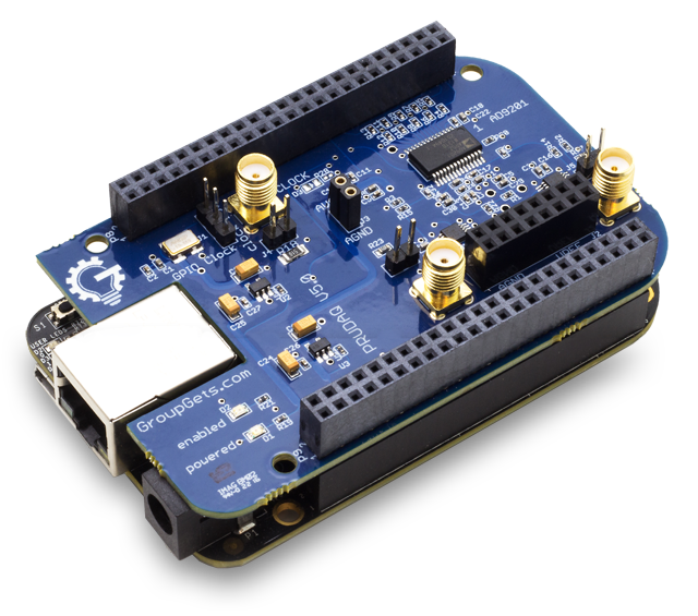
- 2016-08-22: BBB+Probe: Images acquired from a BeagleBone black with a probe (20160822a)
- 2016-08-14: RPi: Testing the acquisition with the BeagleBone DAQ. (20160814a)
- 2016-08-09: Goblin tests: Testing the goblin board with the silent emulator. (20160809a)
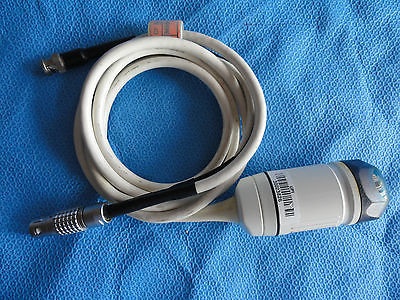
That's the list of probes I've been playing with:
- 724A* BiViPiezo* NDTPiezo* accessa* accessc* adrus* apogee* apogee10MHz* apogee5MHz* atlannular* atlidrict* ausonics75* bard* bk1850* bk8536* brd35* brd75* brd90* clarius* diasonics_50* diasonics_75* diasonics_gpm_plus_35* diasonics_tr* duc2m* hp2121* intersonvs35* ir1510ak* kretzaw145ba* kretzir175ag* linscan* lumify* myapo* retro10PV* retro10apogee* retroATL3* s3* shzmch* sw45b* uprobe1* wirelessdual
Here's a couple of things we're working on, for which you could help as well.
- Boosting the 6Msps croaker acquisition (see Wayne?) to the full 6Msps
- Get one V1.0 board
- Get one V1.1 board (with winbond :p)
- Test new HDL code
- Test david 1.1 code
- Buy headers for VGA (??)
- Do logo
- Do sticker
- Do mini matty
- Do QR code to doc
- PayMeACoffee button
- other readme buttons
- improve readme (and delete home page?)
- Test Goblin v2 (in goblin)
- None (in wirephantom)
- Review a bipolar design (originally alt.tbo -- but double the components and hence the price) (in lite.tbo)
- Improve i2s transfers (in pic0)
- See the next steps (in matty)
- Having it work with a retroATL3 (in matty)
- Improve i2s transfers (in lit3rick)
- PMODs US:
- Documentation - update for lit3 once it is ready, with http://2012.oshwa.org/files/2012/07/Wozniak-OHS2012-Final.pdf, http://2011.oshwa.org/files/2011/09/Wozniak-OHS2011.pdf, and https://cdn-blog.adafruit.com/uploads/2011/09/w0z-OHS2011-v1.pdf
- get https://github.com/tobozo/M5Stack-SD-Updater to add bins
- check artists meet makers
- integrate some documentation for un0rick and lit3rick as in http://www.trenz-electronic.de/fileadmin/docs/Trenz_Electronic/Modules_and_Module_Carriers/3.05x6.5/TE0876/REV02/Documents/iceZero-pinout-v5.pdf
- move forward on some new hardware like the ft600
- FUP i2s w Andrew
- energy harvesting + low power blink
- finalize article
- clear hilbert ImportError: libf77blas.so.3: cannot open shared object file: No such file or directory
The echOmods project and its prototypes are open hardware, and working with open-hardware components.
Licensed under TAPR Open Hardware License (www.tapr.org/OHL)
Copyright Kelu124 (kelu124@gmail.com) 2015-2018
The following work is base on a previous TAPR project, Murgen - and respects its TAPR license.
Copyright Kelu124 (kelu124@gmail.com) 2015-2018
This project is distributed WITHOUT ANY EXPRESS OR IMPLIED WARRANTY, INCLUDING OF MERCHANTABILITY, SATISFACTORY QUALITY AND FITNESS FOR A PARTICULAR PURPOSE.
| ThumbnailImage | Name | In | Out |
|---|---|---|---|
 |
cletus: | ||
 |
toadkiller: | ||
 |
oneeye: | ||
 |
tobo: | ||
 |
mogaba: | ||
 |
croaker: | ||
 |
sleepy: | ||
 |
tomtom: | ||
 |
loftus: | ||
 |
alt.tbo: | ||
 |
retro10PV: |
Note that the 'BONUS!' represents something that could be done, and does not count as a strict TODO.
| Name of module | ToDo | Done | Progress |
|---|
[](@autogenerated - invisible comment)