ScartCable
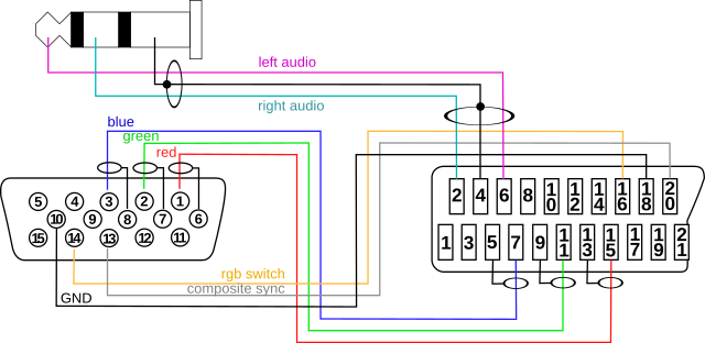
The MIST can be connected to a SCART TV via a VGA to SCART cable. This must be supported by the running core and the core must generate a TV compliant RGB signal with the appropriate composite sync signal in order to allow the TV to correctly pick up the signal. The video signal must be 15kHz and can be 50hz or 60hz.
The generation of a SCART TV (15khz) compliant signal is typically enabled by the following line in the MIST.INI (see the INI file documentation):
scandoubler_disable=1
The scandoubler is the component inside the Core that converts the standard TV signal the original machines generated into a VGA compliant signal. Disabling this component makes cores supporting this to output a signal similar to the one delivered by the original machine.
You can also switch between 15khz and VGA output by holding down the middle button on the MiST.
Most cores support this configuration. Some cores such as Plus Too (Mac) don't support 15khz as their output is too high resolution for 15khz. Atari 800 is a special case that requires a certain core version for the output you want.
Matching cables can be bought e.g. from WOLFSOFT/Germany or from Lotharek or from AMedia Computer.
SCART TVs expect at least five signals: The three analogue colour signals, a composite sync signal and a signal telling the TV to switch into RGB mode. The colour signals are directly taken from the VGA connector and have a similar function as in VGA mode. The composite sync signal (a combination of the H- and VSYNC signals) required by SCART TVs has to be delivered via the VGA connectors HSYNC pin and the RGB switch signal (permanent high) is being taken from the VGA connectors VSYNC signal.
The cable being used for this on the MIST is the same one that was used on the original Minimig. Any "Minimig SCART" cable will thus work.
The MIST provides analogue audio signals on the 3.5mm audio plug. These signals can optionally also be connected to the SCART connector on a TV.
There are various ground connections on the VGA as well as the SCART connector. Some of them are usually being used to shield the colour signals as well as he audio signals. At least the connection between VGA pin 10 and SCART pin 18 is required. But it is recommended to connect the shield connections as well to protect the analogue signals from noise.
Beware that this diagram is for building a male SCART cable.
If you want to make a VGA to female SCART connector adapter, you have to solder SCART audio pins to 1 and 3 instead of 2 and 6 respectively, and SCART sync signal to 19 instead of 20. This is because SCART cables are crossed.

Various similar SCART-to-VGA cables can be found on auction and shopping sites using the "SCART VGA cable" search phrase. Most of these cables are configured to allow to connect equipment like DVD players with SCART output to devices with VGA input (e.g. projectors). These cables are not compatible with the MIST SCART use case since SCART uses separate pins for input and output and a SCART-to-VGA cable differs in direction from a VGA-to-SCART cable. Also the usage of the composite sync and RGB detect signals differ.
Fortunately these cables can be fixed. SCART connectors can usually easily be opened. The pins inside the SCART connector can then carefully be extracted using a pair of telephone pliers and then be reinserted to form the required cable. Unfortunately there are usually no audio connections prepared in these cables.
MiST FPGA - One Chip to Rule Them All
- What is it?
- FAQ
- Board overview
- Installing firmware
- Joystick mapping
- Peripherals
- Projects it is based on
- Rom Management
- Setting up a mist.ini file
- Using a custom font
- Tested Displays/Upscalers
- Troubleshooting
- Videos
- User Videos
- Getting Started
- Current core status
- Joy/Keyboard/On-board Shortcuts
- MIDI support
- SD card setup
- Startup menu
- Atari ST
- Atari ST/STe (mistery)
- Amiga
- Amstrad
- Amstrad - alternative
- Apogee/Radio86RK
- Apple I
- Apple II+
- Apple //e
- Apple Macintosh
- Archimedes
- Atari 800
- BBC Micro
- BK0011M
- Commodore PET
- Commodore VIC-20
- Commodore 64
- Commodore 16/Plus4
- Enterprise
- HT1080Z (TRS80 I clone)
- LM80C
- Mattel Aquarius
- MSX
- Ondra SPO 186
- Oric
- PC (Next186)
- PC (XT)
- Primo
- SAM Coupe
- Sinclair ZX80/ZX81
- Sinclair ZX Spectrum
- Sinclair ZX Spectrum - alternative
- Sinclair ZX Spectrum Next
- Sinclair QL
- TI-99/4A
- Vector06
- Video Technology Laser 350/500/700
- Videoton TVC
- Astrocade
- Atari 2600
- Atari 5200
- Atari 7800
- ColecoVision
- Gameboy
- Genesis/Megadrive
- Intellivision
- Master System
- Neo Geo MVS/AES
- NES
- SNES
- PC Engine/TurboGrafx-16
- Vectrex
- Videopac/Odyssey²
- Videopac/Odyssey² - alternative