Skip to content
New issue

Have a question about this project? Sign up for a free GitHub account to open an issue and contact its maintainers and the community.

By clicking “Sign up for GitHub”, you agree to our terms of service and privacy statement. We’ll occasionally send you account related emails.

Already on GitHub? Sign in to your account

MED 4.0 to .msh or .xml with entities #347

Closed
RemDelaporteMathurin opened this issue Mar 15, 2019 · 68 comments
Closed

MED 4.0 to .msh or .xml with entities #347

RemDelaporteMathurin opened this issue Mar 15, 2019 · 68 comments

Comments

@RemDelaporteMathurin
Copy link

Hi all,

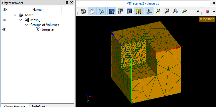
I wish to convert a mesh from SALOME (MED 4.0) to .msh or .xml alongside with cell attributes.

Here's an exemple of a mesh from SALOME with 1 volume marked.
MED.zip

Meshio seems to read it without issues. But, when converting to .msh and after opening it in GMSH, here's the mesh file I get.
gmsh.zip

No sign of the entity "tungsten".

Thanks guys for your help!

Rem

PS: Screenshot of the med file re-imported in SALOME, the group is there as expected.
image

@RemDelaporteMathurin
Copy link
Author

Update:
I tried to convert the MED file to another MED file with meshio, it seems it removed the topological information ...
I'm using SALOME 9.2.2 .

image

@gdmcbain
Copy link
Contributor

Earlier this month we started putting together a test suite of authoritatively generated mesh files #335, e.g. MSH by Gmsh #342. Could this one serve as such an exemplar for MED? I don't know much about MED myself; is Salome its authoritative generator?

@RemDelaporteMathurin
Copy link
Author

I think it is though I'm far from being an expert. Anyway, this one can definitely serve a an exemple.

@RemDelaporteMathurin
Copy link
Author

I noticed in med_io.py, the function read(filename) doesn't seem to take into account groups which should be under FAS. Moreover in write(filename, mesh, add_global_ids=True), the Subgroups seem not to be filled (just the blank fields). The groups seem not be read nor written in any case.
This may be the reason why the groups vanish when converting from MED to MED ?

@nschloe Please correct me if I'm wrong I might have misunderstood something there

@tianyikillua
Copy link
Contributor

@RemiTheWarrior That's correct! I'm not sure if there are already established conventions as how to store node/element groups in a meshio-mesh class...Using these information to write to a MED file should be easy...

@gdmcbain
Copy link
Contributor

Thank you. I won't be able to do too much with this myself over the weekend, away from the office, but I wonder whether this is associated with the conversion of tagged subsets of elements #290 between formats. A neutral representation of these is yet to be established.

@RemDelaporteMathurin
Copy link
Author

@tianyikillua I managed to find some info on MED format here but that's not really precise.

@tianyikillua
Copy link
Contributor

tianyikillua commented Mar 15, 2019

The best way to learn MED is to open MED files using a HDF5 viewer, and happy hacking...I used this way to implement read_data and write_data for MED files...

Concerning MED to MED while reading and writing available node/element groups, it should be possible to do so, in the first time, within the med module, as

A neutral representation of these is yet to be established.

If you are interested feel free. Otherwise I may find some time next week...

@RemDelaporteMathurin
Copy link
Author

Currently downloading HDFView 😉 This is kinda new to me, but I'll definitely try to look into it

@RemDelaporteMathurin
Copy link
Author

Hi all,

Just to say that I found a workaround using for converting .med to .xml using MED 3.2:

  1. Convert from .med to .msh by opening it in GMSH
  2. Convert from .msh to .xml with dolfin-convert

Note that 2) creates as expected 3 .xml files (mesh.xml alongside mesh_facet_region.xml and mesh_physical_region.xml) whereas meshio-convert doesn't and returns this warning:
WARNING:root:DOLFIN XML can only handle one cell type at a time. Using tetra, discarding triangle.

Here are the files.
MED 3.2 generated with SALOME 8.3.0

.msh converted with GMSH 3.0.0

.xml converted with dolfin-convert

@gdmcbain
Copy link
Contributor

Thanks @RemiTheWarrior, this is really useful; I propose to include these into the test suite so that we can test that meshio can correctly perform these conversions too.

This was referenced Mar 16, 2019
@gdmcbain
Copy link
Contributor

@RemiTheWarrior, I notice that Mesh_1_830.med contains 72 2-node line elements which are not in Mesh_1_830.msh. Are they significant? Both contain 270 3-coordinate points (matching to within ±1/10¹³), 438 3-node triangles (identical connectivity), and 839 4-node tetrahedra (same connectivity but with middle two points permuted).

The main difference is of course that the meshio.Mesh read from the MED contains no cell_data or field_data whereas that from your MSH has field_data:

{'top': array([1, 2]), 'bottom': array([2, 2]), 'walls': array([3, 2]), 'tungsten': array([4, 3])}

and cell_data[t]['gmsh:physical'] for t = 'triangle' (438 values in {1, 2, 3}) and tetra (839 values, all 4).

But I just wanted to check about the line-elements before proceeding.

@gdmcbain
Copy link
Contributor

The best way to learn MED is to open MED files using a HDF5 viewer

Another good way is stepping through meshio.med_io.read with pdb.runcall. Doing that, I found f['ENS_MAA']['Mesh_1']['-0000000000000000001-0000000000000000001']['MAI'][t]['FAM'][()] contains:

t n values
'SE2' 72 {0}
'TR3' 438 {-8, -7, -6}
'TE4' 839 {-9}

@gdmcbain
Copy link
Contributor

The corresponding names for the three families of triangles and one family of tetrahedra seem to be encoded in

f['FAS']['Mesh_1']['ELEME'].keys()

<KeysViewHDF5 ['FAM_-6_top', 'FAM_-7_bottom', 'FAM_-8_walls', 'FAM_-9_tungsten']>

and also in, e.g.

f['FAS']['Mesh_1']['ELEME']['FAM_-6_top']['GRO']['NOM'][()]

array([[116, 111, 112, 0, 0, 0, 0, 0, 0, 0, 0, 0, 0,
0, 0, 0, 0, 0, 0, 0, 0, 0, 0, 0, 0, 0,
0, 0, 0, 0, 0, 0, 0, 0, 0, 0, 0, 0, 0,
0, 0, 0, 0, 0, 0, 0, 0, 0, 0, 0, 0, 0,
0, 0, 0, 0, 0, 0, 0, 0, 0, 0, 0, 0, 0,
0, 0, 0, 0, 0, 0, 0, 0, 0, 0, 0, 0, 0,
0, 0]], dtype=int8)

since

 ''.join(map(chr, [116, 111, 112]))

is `'top'. (!)

The 72 2-node line-segments don't seem to belong to any such family.

@gdmcbain
Copy link
Contributor

f['FAS']['Mesh_1']['ELEME']['FAM_-6_top'].attrs['NUM']

-6

@RemDelaporteMathurin
Copy link
Author

RemDelaporteMathurin commented Mar 18, 2019

@gdmcbain

I notice that Mesh_1_830.med contains 72 2-node line elements which are not in Mesh_1_830.msh. Are they significant? Both contain 270 3-coordinate points (matching to within ±1/10¹³), 438 3-node triangles (identical connectivity), and 839 4-node tetrahedra (same connectivity but with middle two points permuted).

Since the mesh can be read into FEniCS I would say they aren't significant.

The main difference is of course that the meshio.Mesh read from the MED contains no cell_data or field_data whereas that from your MSH has field_data:

{'top': array([1, 2]), 'bottom': array([2, 2]), 'walls': array([3, 2]), 'tungsten': array([4, 3])}

and cell_data[t]['gmsh:physical'] for t = 'triangle' (438 values in {1, 2, 3}) and tetra (839 values, all 4).

I don't really know the difference between cell_data and field_data, but the data I'm interested in are the geometrical markers for top, bottom, walls, tungsten, respectively : 1,2,3,4.

f['FAS']['Mesh_1']['ELEME']['FAM_-6_top'].attrs['NUM']

In MED format, several groups (top, bottom, walls, etc.) can belong to a family (eg. FAM_-6_top). In this specific case, you should be able to find a key named GRO containing the attribute NOM.

@nschloe
Copy link
Owner

nschloe commented Mar 18, 2019

I don't really know the difference between cell_data and field_data

field_data is VTK nomenclature. It's data that not associated with other mesh entities, like creation date, description strings, meta things like that. The name field_data is perhaps not well chosen.

@RemDelaporteMathurin
Copy link
Author

entities should be stored in cell_data then?

@nschloe
Copy link
Owner

nschloe commented Mar 18, 2019

Depends on what you mean by "entities". Cell data is data associated with cells.

@RemDelaporteMathurin
Copy link
Author

Sorry for that, by entity I mean this information

{'top': array([1, 2]), 'bottom': array([2, 2]), 'walls': array([3, 2]), 'tungsten': array([4, 3])}

assigned for every cell and facet. In other words, "mark" the cells and facets with their topological information. Above, the all the facets belonging to surface top are marked 1 and all the cells belonging to volume tungsten are marked 4. Is this more clear ?

@nschloe
Copy link
Owner

nschloe commented Mar 18, 2019

Is this more clear ?

Not to me.

assigned for every cell and facet. I

Every cell and facet has all the information? No. What does 'top': array([1, 2]) mean? Cells 1 and 2 are on the top? Or facets 1 and 2?

@RemDelaporteMathurin
Copy link
Author

RemDelaporteMathurin commented Mar 18, 2019

Every cell and facet has all the information? No. What does 'top': array([1, 2]) mean? Cells 1 and 2 are on the top? Or facets 1 and 2?

Should have said "assigned for each cell", sorry. 'top': array([1, 2]) means that the group "top" is of dimension 2, and marked with the int 1.

@nschloe
Copy link
Owner

nschloe commented Mar 18, 2019

'top': array([1, 2]) means that the group "top" is of dimension 2, and marked with the int 1.

Ah, okay. So that's not really cell data. I think we should find a better name for the field_data, perhaps meta_data or extra_data or something. @gdmcbain What do you think?

@tianyikillua
Copy link
Contributor

BTW I've never understood field_data 😄

@nschloe
Copy link
Owner

nschloe commented Mar 18, 2019

Yeah, sorry guys! Here's the extract from the VTK manual:

vtk

@tianyikillua
Copy link
Contributor

tianyikillua commented Mar 18, 2019

Okay...as you mentioned it I've indeed seen this thing under ParaView...

Returning to reading/writing point/cells sets from a MED file. The first is easy, we just need to create a new dict point_set similar to point_data. Noting that in general a same node can indeed belong to differents node sets, so point set name -> point index is appropriate.

mesh.point_set = {"set A": [0, 5, 19], 3: [2, 5, 9]}

so the point set "set A" contains indices 0, 5 and 19, while the point set 3 contains indices 2, 5 and 9, the node 5 belonging to both "set A" and 3.

@tianyikillua
Copy link
Contributor

tianyikillua commented Mar 18, 2019

Concerning cell sets, I'm in favor of storing directly cell indices instead of indicator functions of each regions...as @nschloe put it in #175 (comment), since "it permits cells to be a member of an arbitrary number of regions (also none at all)". With MED, I think (to be verified) this is indeed the case, where a same cell can belong to several cell sets.

Then two possibilities (#175 (comment)):

  1. Like cell_data: cell_type -> cell set name -> cell index
mesh.cell_set = {
    "tetra": {"set A": [0, 1, 3], 1: [1, 2]},
    "triangle": {"set B": [3, 5], 3: [0]},
    "quad": {"set C": [1, 4], 3: [0, 5, 9]},
}

where the cell set 3 is a mixed set: it contains the first triangle, and quad indices 0, 5 and 9...This set can for instance used for prescribing pressure for 3d simulations.

Also tetra index 1 belongs to two sets: "set A" and 1.

  1. Or doing cell set name -> cell_type -> cell index
mesh.cell_set = {
    "set A": {"tetra": [0, 1, 3]},
    1: {"tetra": [1, 2]},
    "set B": {"triangle": [3, 5]},
    "set C": {"quad": [1, 4]},
    3: {"triangle": [0], "quad": [0, 5, 9]}
}

Maybe the 2nd way is more readable, since in parallel with point_set we will have

  • point_set: point set name -> point index
  • cell_set: cell set name -> cell_type -> cell index

PS: I omitted some hexa cells...

@gdmcbain
Copy link
Contributor

you should be able to find a key named GRO containing the attribute NOM.

Yes. See above.

I guess that these stand for groupe (=group) and nom (=name).

@RemDelaporteMathurin
Copy link
Author

the original MED file with lots of groups (and unions of groups) can NOT be read by gmsh.

If you're using the very last version of SALOME (9.2.2) there's a known bug which automatically exports .med in version 4.0. MED 4.0 cannot be read by GMSH whether there are groups or not. So far.

I used an older version of SALOME in order to produce the example above. I'm not sure that the number of groups is an issue as long as they don't overlapp one another.

Moreover, in the conversion above, I noticed that if all the cells aren't in a group, GMSH just ignores this cell, resulting in a hollow mesh.

@tianyikillua
Copy link
Contributor

tianyikillua commented Mar 19, 2019

So for MED, there are two possibilities of implementing cell sets, node sets being trivial.

  1. Using user-defined sets and internally created intersections sets for overlapped sets to define a element -> region id (currently done in meshio via gmsh_physical as a cell_data and in MED file internally, through FAM)
  2. Go deeper into this element -> region id by decomposing possible intersections sets, and associate several groups to the same node/element if it is the case. Construct a mesh.cell_set.

@tianyikillua
Copy link
Contributor

tianyikillua commented Mar 19, 2019

the original MED file with lots of groups (and intersections of groups) can NOT be read by gmsh.

If you're using the very last version of SALOME (9.2.2) there's a known bug which automatically exports .med in version 4.0. MED 4.0 cannot be read by GMSH whether there are groups or not. So far.

I used an older version of SALOME in order to produce the example above. I'm not sure that the number of groups is an issue as long as they don't overlapp one another.

Moreover, in the conversion above, I noticed that if all the cells aren't in a group, GMSH just ignores this cell, resulting in a hollow mesh.

Oh thanks! You were right. Below is the same cylinder MED file, where the version is changed from 4.0.0 to 3.0.0, by modifying manually INFOS_GENERALES.

Cylinder_3_0_0.zip

This file can be loaded by gmsh (it and knows treating overlapping sets and elements belonging to different groups, I think).

Using gmsh to convert MED to msh, and read this msh using meshio gives the above figure.

  • gmsh:geometrical is the element id -> region id map, with some intersection sets
  • gmsh:physical is all 0, since we don't know how to treat elements belonging to several groups (good job)
  • field_data is
{'Top circle': array([4, 1]),
 'Top': array([5, 2]),
 'Top and down': array([6, 2]),
 'B': array([1, 3]),
 'A': array([2, 3]),
 'C': array([3, 3])}

which is not useful since gmsh:physical is all 0. Where is the field_data for gmsh:geometrical?

@RemDelaporteMathurin
Copy link
Author

  • gmsh:physical is all 0, since we don't know how to treat elements belonging to several groups (good job)

@tianyikillua So we're able to read those belonging to only one group then ?

@tianyikillua
Copy link
Contributor

  • gmsh:physical is all 0, since we don't know how to treat elements belonging to several groups (good job)

@tianyikillua So we're able to read those belonging to only one group then ?

Cylinder_no_overlap_groups_3_0_0.zip

Sadly no...still 0 everywhere. In the msh file the elements refer to the gmsh:geometrical region, which doesn't match gmsh:physical contained in field_data.

@tianyikillua
Copy link
Contributor

tianyikillua commented Mar 21, 2019

In MED (also gmsh in fact) we can give the same name to different sets corresponding to different manifold dimensions (so Top can be used to group all 2d elements on the top, and some 1d elements on the top), internally MED will just assign another unique set id.

So this motivates me to use the unique element set id's as keys in the mesh.tags (aka your field_data).

Reading the gmsh-converted .msh file containing two different sets with a same name leads to one being eaten by the other. So maybe we also need to redesign your field_data?

@gdmcbain
Copy link
Contributor

Reading the gmsh-converted .msh file containing two different sets with a same name leads to one being eaten by the other. So maybe we also need to redesign your field_data?

Yes that does sound like a shortcoming in the Gmsh reader, especially if that failing file is actually output by Gmsh itself. Is that MSH2.2? Could you launch an issue and attach a minimal failing example?

@gdmcbain
Copy link
Contributor

On the other hand, just because a format permits something doesn't mean it's likely to arise in practice. Is there much chance of a sensible MED or Gmsh user presenting such a file?

@RemDelaporteMathurin
Copy link
Author

RemDelaporteMathurin commented Mar 21, 2019

I reckon it will always be possible to do whatever you want by assigning 1 cell to 1 group (no overlapping). If you want to apply a BC to 2 surfaces (top and bottom let's say) in FEniCS for example, you can apply to BCs to 1 surface each easily ... Don't you agree @tianyikillua ?

@tianyikillua
Copy link
Contributor

tianyikillua commented Mar 21, 2019

Yes of course, technically we don't need overlapping groups, but sometimes for modeling purposes we could need them, see #347 (comment). If we had used the non-intersecting Top and Down, then on Top, the engineer would have to manually superpose himself the two pressure loads.

@RemDelaporteMathurin
Copy link
Author

Well, let's take the commercial software COMSOL for example: when you need to apply a BC to several surfaces, you have to select each surface one by one. It's not that time consuming in the end, except if you have plenty of surfaces, but even in this case, the user would have to select them in SALOME (or any meshing software) one by one in order to group them into 'Top and Down'.

@tianyikillua
Copy link
Contributor

Yes I see your point. So an experienced engineer has to choose

  • Either simplifies the surface selection work during CAD/set tagging (by choosing one surface at a time), and then eventually complicates himself when apply loads of different nature
  • Either selects more surfaces (even duplicated ones) during CAD/set tagging, and then maybe applying more easily and physically the loads

We should allow these two possibilities...

@RemDelaporteMathurin
Copy link
Author

That's true. But one bird in the hand is worth two in the bush. Currently the user can't do either of the two possibilities 😉

@tianyikillua
Copy link
Contributor

Yes better an egg today than a hen tomorrow, and take the cash and let the credit go.

In #352 (comment), it may be now possible to take your egg and cash.

@RemDelaporteMathurin
Copy link
Author

Hi all, finally got time to test all the work you've done @tianyikillua. I ran into some issues:

  1. converting from med to xdmf:

when I try to import the mesh in FEniCS, I get an error caused by the "mixed" value - but that was expected.

med_to_xdmf.zip

  1. converting from med to msh then doflin-convert to xml or xdmf:

I get the following error:

Converting from Gmsh format (.msh, .gmsh) to DOLFIN XML format
Traceback (most recent call last):
  File "/usr/local/bin/dolfin-convert", line 132, in <module>
    main(sys.argv[1:])
  File "/usr/local/bin/dolfin-convert", line 79, in main
    meshconvert.convert2xml(ifilename, ofilename, iformat=iformat)
  File "/usr/local/lib/python3.6/dist-packages/dolfin_utils/meshconvert/meshconvert.py", line 1301, in convert2xml
    convert(ifilename, XmlHandler(ofilename), iformat=iformat)
  File "/usr/local/lib/python3.6/dist-packages/dolfin_utils/meshconvert/meshconvert.py", line 1322, in convert
    gmsh2xml(ifilename, handler)
  File "/usr/local/lib/python3.6/dist-packages/dolfin_utils/meshconvert/meshconvert.py", line 261, in gmsh2xml
    line = ifile.readline()
  File "/usr/lib/python3.6/codecs.py", line 321, in decode
    (result, consumed) = self._buffer_decode(data, self.errors, final)
UnicodeDecodeError: 'utf-8' codec can't decode byte 0xb8 in position 57: invalid start byte

Don't know if it's a fenics-related issue or again caused by the "mixed" value.
med_to_msh.zip

  1. converting from med to xml:
    Creates 2 files: mesh.xml and mesh_cell_tags.xml
    When I try to import mesh.xml : no problem at all.
    When I try to import mesh_cell_tags.xml I get the following error:
Traceback (most recent call last):
  File "meshfunction.py", line 30, in <module>
    subdomains = MeshFunction("size_t", mesh, "test_cell_tags.xml")
  File "/usr/local/lib/python3.6/dist-packages/dolfin/mesh/meshfunction.py", line 18, in __new__
    return fn(mesh, dim)
RuntimeError:

*** -------------------------------------------------------------------------
*** DOLFIN encountered an error. If you are not able to resolve this issue
*** using the information listed below, you can ask for help at
***
***     fenics-support@googlegroups.com
***
*** Remember to include the error message listed below and, if possible,
*** include a *minimal* running example to reproduce the error.
***
*** -------------------------------------------------------------------------
*** Error:   Unable to read mesh function from XML file.
*** Reason:  Type mismatch reading XML MeshFunction. MeshFunction type is "uint", but file type is "int".
*** Where:   This error was encountered inside XMLMeshFunction.h.
*** Process: 0
***
*** DOLFIN version: 2018.1.0
*** Git changeset:  948dc42cc4e06ed9227d0201ad50f94ac94cbf9f
*** -------------------------------------------------------------------------

med_to_xml.zip

@tianyikillua
Copy link
Contributor

Could you please try #352 (comment)? You need to manually separate and export line and face elements, with appropriate tags.

Also, don't forget to take the absolute values of cell_tags as FEniCS prefers natural numbers size_t.

@RemDelaporteMathurin
Copy link
Author

Ah really sorry about that, missed that one. Do you know if it'd work in 2D as well ? I should just replace tetra by triangle and triangle by line, am I right ?

@tianyikillua
Copy link
Contributor

Yes, and for triangular meshes include also cell_tags if you want to define different material behaviors for instance.

@RemDelaporteMathurin
Copy link
Author

@tianyikillua, it couldn't work better. Thanks for all the work guys!

@smickleborough
Copy link

Hi, i'm using gmesh and meshio for FEM and I'd like to get the node coordinates etc of my physical groups to apply BC's . I thought mesh.field_data could be used but from reading this thread it seems I am wrong. Are you saying that there is no way I can do this and that the named regions are essentially useless?

@nschloe
Copy link
Owner

nschloe commented Dec 2, 2019

@smickleborough Look at point_data, cell_data.

@smickleborough
Copy link

Thanks, i think I've got it now.

@GuangjinM
Copy link

Hi all,

Just to say that I found a workaround using for converting .med to .xml using MED 3.2:

  1. Convert from .med to .msh by opening it in GMSH
  2. Convert from .msh to .xml with dolfin-convert

Note that 2) creates as expected 3 .xml files (mesh.xml alongside mesh_facet_region.xml and mesh_physical_region.xml) whereas meshio-convert doesn't and returns this warning: WARNING:root:DOLFIN XML can only handle one cell type at a time. Using tetra, discarding triangle.

Here are the files. MED 3.2 generated with SALOME 8.3.0

.msh converted with GMSH 3.0.0

.xml converted with dolfin-convert

i would like to know how can i get the facet_region information?

Sign up for free to join this conversation on GitHub. Already have an account? Sign in to comment
Labels
None yet
Projects
None yet
Development

No branches or pull requests

6 participants