WM240 Battery Intelligent Board
Function
Variants
Parts
Programming
External interfaces
Service interfaces
Board view
Schematics
DJI Intelligent Flight Battery for Mavic 2 is a 3850mAh, 15.4V LiPo-4s battery, supporting up to 31 minutes of flight time. The battery also has built-in sensors and LEDs which let you know the status and remaining power. It contains automatic discharge feature to avoid swelling (fully charged LiPo cells release hydrogen), and Permanent Failure feature which disables the battery in case of damage or unexpected behavior of cells.
The battery management system chip (TI BQ9003) communicates with FC directly, through Smart Battery System protocol, with some small modifications introduced by DJI.
The SBS protocol defines battery-related commands to be transferred over SMBus, which in turn is deviced from I2C.
There are multiple versions of the board.
| Marking | Overview |
|---|---|
| PP000062.05 |
| Marking | Amt. | Pkg. | Function | Specification |
|---|---|---|---|---|
| BQ9003 | 1 | TSSOP-30 | Li-Ion Battery Pack Manager; the specific chip was only made available by TI for a few customers, but it is relatively similar to BQ40Z50. The DJI-modified firmware presents the chip as BQ40z307. | |
| 1C530l Prm 1829 C2 481000 | 4 | Nexperia N-channel 30V 1.55mOhm logic level MOSFET in LFPAK using NextPower technology | description | |
| 102 | 1 | SMD Resistors | ||
| 2m0 | 2 | SMD Resistors | ||
| CD | 1 | |||
| 10-slab EXT PWR CON | 1 | MSD-DB05F-10P, MISTA pitch 2.5mm 10 slab connector | description | |
| 5-pin BAL CON | 1 | Molex 53261-7005 PicoBlade pitch 1.25mm 5 pin connector | description | |
| 8-pin IFC FFC CON | 1 | FFC pitch 0.5mm 8 pin connector |
| Chips | Firmware | Description |
|---|---|---|
| BQ9003 | m1100 | Battery Management System chip firmware. |
Connectors on the board are:
| Marking | Overview |
|---|---|
| 10-slab EXT PWR CON | External connector of the battery; provides power input and output, and serial interface. |
| 5-pin BAL CON | Cells balancing connector. |
| 8-pin IFC FFC CON | Interface connector, for charge level LEDs and power button. |
Here is the connector pinout:
| Pin | Label | Function |
|---|---|---|
| 1 | PACK+ | +15.4V from battery cells |
| 2 | PACK+ | |
| 3 | PACK+ | |
| 4 | PACK+ | |
| 5 | SDA | SMBus data line |
| 6 | SCL | SMBus clock line |
| 7 | GND | Ground for both the PACK+ and the SMBus |
| 8 | GND | |
| 9 | GND | |
| 10 | GND |
Here is the connector pinout:
| Pin | Label | Function |
|---|---|---|
| 1 | GND | |
| 2 | CELL1 | |
| 3 | CELL2 | |
| 4 | CELL3 | |
| 5 | CELL4 |
Here is the connector pinout:
| Pin | Label | Function |
|---|---|---|
| 1 | GND | Ground |
| 2 | B_I | Safety Switch In |
| 3 | B_O | Safety Switch Out |
| 4 | RL_0 | LED ctrl 0 |
| 5 | RL_1 | LED ctrl 1 |
| 6 | RL_2 | LED ctrl 2 |
| 7 | KEY | Main Power button (pulled high by default) |
| 8 | GND | Ground |
The following service pads exist on this board:
| Marking | Overview |
|---|---|
| TODO |
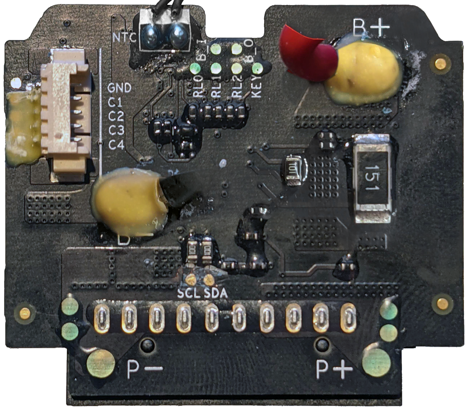
Top of a PP000062.05 board:

Bottom of the PP000062.05 board:
flowchart LR
    Connector-BAT((batt<br/>connec<br/>tor))
    subgraph Battery Intelligent board
    direction LR
    BatteryBMS[BQ9003 BMS<br/>Li-Ion pack<br/>manager]
    BattFeedbackR(0.01 Ohm<br/>feedback<br/>resistor)
    EnablePackFET(MOSFET<br/>output<br/>control)
    EnableChargeFET(MOSFET<br/>charge<br/>enable)
    EnableDischargeFET(MOSFET<br/>internal<br/>discharge<br/>enable)
    DischargeR(discharge<br/>resistor)
    DischargeR---EnableDischargeFET
    BatteryBMS-- DSG ---EnableDischargeFET
    BatteryBMS-- PCHG ---EnablePackFET
    BatteryBMS-- CHG ---EnableChargeFET
    end
    subgraph Batt.Iface brd
    BatteryButton(button)
    BatteryLEDs(LEDs)
    end
    BatteryButton---BatteryBMS
    BatteryLEDs---BatteryBMS
    subgraph Li-Po cells pack
    direction TB
    BatteryCell1(battery<br/>cell 1)
    BatteryCell2(battery<br/>cell 2)
    BatteryCell3(battery<br/>cell 3)
    BatteryTempSense(NTC<br/>thermistor)
    BatteryCell1===BatteryCell2
    BatteryCell3===BatteryCell2
    end
    BattFeedbackR===BatteryCell1
    BatteryBMS-- VSS ---BatteryCell1
    BatteryBMS---BatteryCell2
    BatteryBMS---BatteryCell3
    Connector-BAT== PACK- ===BattFeedbackR
    BatteryBMS-- SRn ---BattFeedbackR
    BatteryBMS-- TS ---BatteryTempSense
    EnableDischargeFET===BatteryCell3
    EnablePackFET===EnableDischargeFET
    EnableChargeFET===EnableDischargeFET
    Connector-BAT== PACK+ ===EnablePackFET
    Connector-BAT== PACK+ ===EnableChargeFET
    Connector-BAT-- SMBus ---BatteryBMS
Thick lines are the ones transferring high power. Feedback resistor for measuring current is inserted into negative line, while all the MOSFET switches are within positive line. The three Li-Po cells are connected in series, so that the voltage sums up.
The Battery Management System chip supports status LEDs and a button, which are placed on separate interface board. The output connector includes SMBus lines, which allow to exchange packets described in Smart Battery Specification, as well as some DJI-specific extensions.
The charge level, as well as errors and faults detected within the BMS, can be shown on four LEDs. Specifics of how the interface and the buttons work, as well as extensions to the SBS protocol, require implementation within the BMS firmware. Therefore, the firmware is not a stock TI version, but a modification of TIs firmware code by DJI engineers.
No schematics available.