
This software streams games from a Raspberry Pi to a Game Boy Advance, through its Link Port. Video and audio are compressed and sent in real time to the GBA, while the latter responds with its current input, allowing users to play games of any platform by using the GBA (hence, Remote Play).
Features:
- Plays any game using RetroPie on the GBA!
- 120x80 pixels of power!
- ~60fps using the default display mode
- Retro scanlines 😎
- More pixels of power on overclocked GBAs
- Experimental audio support!
Crashes on the GB Micro! (yep, that's a feature)
Created by [r]labs.
Check out my other GBA projects!
- piuGBA: A PIU emulator 💃
↙️ ↖️ ⏹↗️ ↘️ 🕺 - gba-link-connection: A multiplayer library 🎮🔗🎮
demo.mp4
video-only.mp4
video-and-audio.mp4
⚠️ This section will talk about implementation details. For setup instructions, scroll down to Setup!⚠️
Basically, there are two programs:
- On the GBA, a ROM that receives data.
- On the RPI, a program that collects and sends data.
The ROM is sent to the GBA by using the multiboot protocol, which allows small programs to be sent via Link Cable. No cartridge is required.
Communication is done through a GBA's Link Cable, soldered to the Raspberry Pi's pins.
GBA Link Cable's pinout
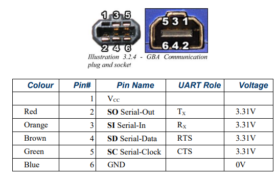
The GBA supports several serial communication modes. Depending on which mode you use, the pins will behave differently. The most common ones are:
- Normal Mode: It's essentially SPI mode 3, but they call it "Normal mode" here. The transfer rate can be either 256Kbit/s or 2Mbit/s, and packets can be 8-bit or 32-bit.
- Multiplayer Mode: What games normally use for multiplayer with up to 4 simultaneous GBAs. The maximum transfer rate is 115200bps and packets are always 16-bit.
- General Purpose Input/Output: Classic GPIO, used for controlling LEDs, rumble motors, and that kind of stuff.
To have a decent frame rate, this project uses the maximum available speed: that's Normal Mode at 2Mbps, with 32-bit transfers.
SPI is a synchronous protocol supported by hardware in many devices, that allows full-duplex transmission. There's a master and a slave, and when the master issues a clock cycle, the two devices send data to each other (one bit at a time).
SPI cycle

This is what happens on an SPI cycle. Both devices use shift registers to move bits of data circularly. You can read more about the data transmission protocol here.
The GBA can work both as master or as slave, but the Raspberry Pi only works as master. So, the Raspberry controls the clock.
As for the connection, only 4 pins are required for the transmission: CLK (clock), MOSI (master out, slave in), MISO (master in, slave out), and GND (ground).
- On the GBA, these are Pin 5 (SC), Pin 3 (SI), Pin 2 (SO), and Pin 6 (GND).
- On the RPI, these are GPIO 11 (SPI0 SCLK), GPIO 10 (SPI0 MOSI), GPIO 9 (SPI0 MISO), and one of its multiple GNDs.
GBA <-> Raspberry Pi connection diagram

Some peculiarities about GBA's Normal Mode:
- When linking two GBAs, you need to use a GBC Link Cable. If you use a GBA one, the communication will be one-way: the slave will receive data but the master will receive zeroes.
- Communication at 2Mbps is only reliable when using very short wires, as it's intended for special expansion hardware.
Related code:
- SPIMaster on the Raspberry Pi
- SPISlave on the GBA
- SPIMaster on the GBA (used for the GBA Jam demo)
In my tests with a Raspberry Pi 3, the maximum transfer rates I was able to achieve were:
- Bidirectional: 1.6Mbps. From here, the Raspberry Pi starts receiving garbage from the GBA.
- One-way: 2.6Mbps. Crank this up, and you'll have corrupted packets.
- One-way, on an overclocked GBA: 4.8Mbps, using a 12Mhz crystal oscillator instead of the default one (4.194Mhz).
One-way transfers are fine in this case, because we only care about input and some sync packets from the GBA. That means that the code is constantly switching between two frequencies depending on whether it needs a response or not. In all cases the Raspberry Pi has to wait a small number of microseconds to let the poor GBA's CPU rest.
Speed benchmark

The first dot means 40000 packets/second and each extra dot adds 5000 more. At maximum speed, they should be all green. The one at the right indicates if we're free of corrupted packets. If it's red, adjust!
Related code:
In classic SPI, the master blindly issues clock cycles and it's responsibility of the slave to catch up and process all packets on time. But here, sometimes the GBA is very busy doing things like putting pixels on screen or whatever it has to do, so it needs a way to tell the master to stop.
As recommended in the GBA manual, the slave can put MISO on HIGH when it's idle, and master can read its value as a GPIO input pin and wait to send until it's LOW.
Pls don't send me anything

Related code:
First, we need to configure Raspbian to use a frame buffer size that matches the GBA's resolution: 240x160. There are two properties called framebuffer_width and framebuffer_height inside /boot/config.txt that let us change this.
Linux can provide all the pixel data shown on the screen (frame buffers) in devfiles like /dev/fb0. That works well when using desktop applications, but not for fullscreen games that use OpenGL -for example-, since they talk directly to the Raspberry Pi's GPU. So, to gather the colors no matter what application is running, we use the dispmanx API (calling vc_dispmanx_snapshot(...) once per frame), which provides us a nice RGBA32 pixel matrix with all the screen data.
Here's one of the many ways of reading the frame buffer wrong

Related code:
Instead of RGBA32, the GBA understands RGB555 (or 15bpp color), which means 5 bits for red, 5 for green, and 5 for blue with no alpha channel. As it's a little-endian system, first one is red.
To draw those colors on the screen, it supports 3 different bitmap modes. For this project, I used mode 4, where each pixel is an 8-bit reference to a palette of 256 15bpp colors. The only consideration to have when using mode 4 is that VRAM doesn't support 8-bit writes, so you have to read first what's on the address to rewrite the complete halfword/word.
15bpp color representation

Related code:
So, the Raspberry Pi has to quantize every frame to a 256 colors palette. In an initial iteration, I was using a quantization library that generated the most optimal palette for each frame. Though that's the best regarding image quality, it was too slow. The implemented solution ended up using a fixed palette (this one in particular), and approximate every color to a byte referencing palette's colors.
|
Original image
|
Quantized image
|


To approximate colors faster, when running the code for the first time, it creates a 16MB lookup table called "palette cache" with all the possible color convertions. It's 16MB because there are 2^24 possible colors and each palette index is one byte.
Related code:
- 15bpp palette on GBA
- 24bpp palette on RPI
- Closest color math
- Palette cache
- JS code used to construct the table
The frame buffer is 240x160 but what's sent to the GBA is configurable, so if you prefer a killer frame rate over detail you can send 120x80 and use the mosaic effect to scale the image so it fills the entire screen. Or, if you like old CRTs, you could send 240x80 and draw artificial scanlines between each actual line.
The Raspberry Pi discards each pixel that is not a multiple of the drawing scale. For example, if you use a 2x width scale factor, it will discard odd pixels and the resulting width will be 120 instead of 240.
At the time of rendering, you have to take this into account because GBA's mode 4 expects a 240x160 pixel matrix. If you give it less, you'd only fill a part of the screen.
|
No scaling
|
2x mosaic
|
Scanlines
|


Here are 3 ways of scaling the same 120x80 clip.
Related code:
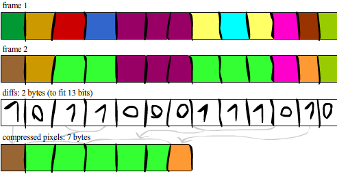
The code only sends the pixels that changed since the previous frame, and what "changed" means can be configured: there's a "compression" (diff threshold) parameter in the runtime configuration that controls how far should be a color to the previous one in order to refresh it.
At the compression stage, it creates a bit array where 1 means that a pixel did change, and 0 that it didn't. Then, it sends that array + the pixels with '1'.
Example of a 13x1 diff array
Related code:
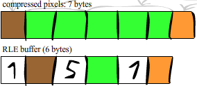
The resulting buffer of the temporal compression is run-length encoded.
When using paletted images, it's highly likely that there are consecutive pixels with the same color. Or, for example, during screen transitions where all pixels are black, instead of sending N black pixels (N bytes) we can send 1 byte for N and then the black color (2 bytes). That's RLE.
However, RLE doesn't always make things better: it can sometimes produce a longer buffer than the original one because it has to add the "count" byte for every payload byte. For that reason, the encoding is made of two stages, and it only applies RLE if it helps compressing the data. Then, the frame's metadata stores a bit that represents if the payload is RLE'd or not.
Encoding the compressed buffer
Related code:
For a render resolution of 120x80, the bit array would be 120x80/8 = 1200bytes. That's a lot to transfer every frame, so it only sends the chunk from the first '1' to the last '1', but of course in 32-bit packets.
                                                                v startPacket                   v endPacket
PACKET 0                        PACKET 1                        PACKET 2                        PACKET 3                        PACKET 4                        PACKET 5
BYTE 0  BYTE 1  BYTE 2  BYTE 3  BYTE 4  BYTE 5  BYTE 6  BYTE 7  BYTE 8  BYTE 9  BYTE 10 BYTE 11 BYTE 12 BYTE 13 BYTE 14 BYTE 15 BYTE 16 BYTE 17 BYTE 18 BYTE 19 BYTE 20 BYTE 21 BYTE 22 BYTE 23
00000000000000000000000000000000000000000000000000000000000000000000000000100100110010000000000001000000000000000000000000000000000000000000000000000000000000000000000000000000000000000000000
                                                                          ^ startPixel           ^endPixel
                                                                ^^^^^^^^^^^^^^^^^^^^^^^^^^^^^^^^^^^^^^^^^^^^^^^^^^^^^^^^^^^^^^^^ packetsToSend

// 24x1 screen
maxPackets = 6
startPixel = 74
startPacket = startPixel / 8 / 4 = 2
endPixel = 97
endPacket = endPixel / 8 / 4 = 3
totalPackets = endPacket - startPacket + 1;
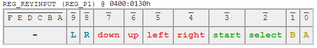
Each frame, the GBA sends its pressed keys to the Raspberry Pi. It does so by reading REG_KEYINPUT and transferring it on the initial metadata exchange.
Bits are set when a key is **not** pressed. Weird design!
In Linux, there's /dev/uinput which lets user space processes create virtual devices and update its state. You can create your virtual gamepad however you like, for example, adding analog sticks and then mapping GBA's D-pad to analog values.
The first implementation was just registering a simple gamepad with the same layout as the GBA. The last version allows users to define a controls.cfg file with key combos, so games with more complex button requirements are also supported.
Related code:
At the beginning, there's a Reset packet sync.
Then, for every frame, the steps to run are:
- (Reset if needed)
- Build frame (RPI only)
- Sync frame start
- Metadata exchange
- (If the frame has audio, sync and transfer audio)
- Sync pixels start
- Transfer pixels
- Sync frame end
- Render (GBA only)
Related code:
Part of the runtime configuration is sent in this reset packet:
10011001100010000111000000000000
____________________^###****$$$$
|                   ||  |   |
 > magic number     ||  |    > render mode: frame width and height
                    ||   > control layout: defined in the configuration file
		    | > compression: affects temporal diffs' threshold
		     > CPU overclock flag: if 1, it uses overclocked SPI timings
Runtime configuration menu

Related code:
In this step, the GBA sends its input and receives a frame metadata packet:
00000000000000000000000000000000
^#**************$$$$$$$$$$$$$$$$
|||             |
|||              > start pixel index (for faster GBA rendering)
|| > number of expected pixel packets
| > compressed flag: if 1, the frame is RLEncoded
 > audio flag: if 1, the frame includes an audio chunk
As a sanity check, this transfer is done twice. The second time, each device sends the received packet during the first transfer. If it doesn't match => Reset!
Related code:
For the audio, the GBA runs a port of the GSM Full Rate audio codec. It expects 33-byte audio frames, but in order to survive frame drops, GSM frames are grouped into chunks, with their length defined by a build time constant called AUDIO_CHUNK_SIZE.
Related code:
On the Raspberry Pi side, we use a virtual sound card that is preinstalled on the system. When you start the module (sudo modprobe snd-aloop), two new sound devices appear (both for playing and recording).
|
Playback audio devices
|
Capture audio devices
|
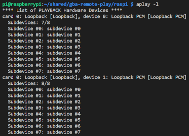
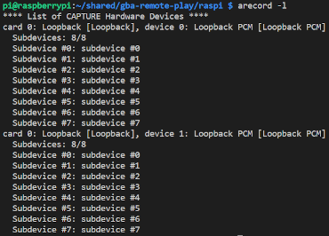
How it works is that if some application plays sound on -for example- hw:0,0,0 (card 0, device 0, substream 0), another application can record on hw:0,1,0 and obtain that sound. The loopback cards have to be set as the default output on the system, so we can record whatever sound is running on the OS.
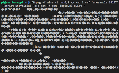
GSM encoding is done with ffmpeg. The GBA port requires a non-standard rate of 18157Hz, so we have to tell it to ignore its checks, like "yeah, this is not officially supported, I don't care", as well as the new rate.
This is what the recording command looks like:
ffmpeg -f alsa -i hw:0,1 -y -ac 1 -af 'aresample=18157' -strict unofficial -c:a gsm -f gsm -loglevel quiet -
I swear this is audio!
Related code:
The - at the end of the ffmpeg command means "send the result to stdout". The code launches this process with popen and reads through the created pipe.
Since transferring a frame takes time, it can sometimes happen that more audio frames are generated than what we can actually use. If we don't do anything about it, when reading the pipe we'd be actually reading audio from the past, producing a snowball of audio lag!
Our GBA vibing to outdated audio frames

To fix that, there's an ioctl we can use (called FIONREAD) to retrieve the amount of queued bytes. To skip over those, we call the splice system call to redirect them to /dev/null.
Related code:
This was the most complex part of the project. Drawing pixels on the bitmap modes is already a lot of work for the GBA, and now it has to decompress GSM frames! Also, it can't lag. Lots of people tolerate low frame rates on video, but I don't think of anyone who can find acceptable hearing high pitch noises or even silence between audio samples.
What I understand GSMPlayer does, is decoding GSM frames, putting the resulting audio samples in a double buffer, and setting up DMA1 to copy them to a GBA's audio address, by using a special timing mode that syncs the copy with Timer 0.
Me attempting to modify GSMPlayer code

Audio must be copied on time to prevent stuttering, noises, etc. Regular games do this by using VBlank interrupts, but that doesn't work here. When transferring at 2.6Mbps there are very few cycles available to process data, and adding an interrupt handler just messes up the packets.
I had to make it so every transfer is cancellable: if it's time to run the audio (we're on the VBlank part), we stop everything, run the audio, and then start a recovery process where we say to the Raspberry Pi where we're at. On start, end, and every TRANSFER_SYNC_PERIOD packets of every stream, the Raspi sends a bidirectional packet (at the slow rate) to check if it needs to start the "recovery mode".
Related code:
The GBA code can optionally overclock the external RAM, to use only one wait state instead of two. This process crashes on a GB Micro, but who would use this on a Micro anyway?
A guy using a GB Micro with a Raspberry Pi attached to it

Related code:
build-guide.mp4
- Solder a Link Cable to the Raspberry Pi according to the Normal Mode / SPI section of this document.
- Install RetroPie.
- Go to RetroArch options and set:
- Settings -> Video -> Scaling -> Aspect ratio -> 4:3
- Configuration File -> Save current configuration
- Run
sudo raspi-configand set:- Interface Options: Enable SPI
- Run
sudo apt-get install -y wiringpi python-pigpio python3-pigpio - Add the following attributes to
/boot/config.txt:
# Set Aspect Ratio (4:3)
hdmi_safe=0
disable_overscan=1
hdmi_group=2
hdmi_mode=6

# Set GBA Resolution
framebuffer_width=240
framebuffer_height=160
- Download the required files (from the Releases section of this GitHub repo) to
/home/pi/gba-remote-play. - From that directory, run:
chmod +x gbarplay.sh multiboot.tool raspi.run. - Edit
/etc/rc.localand add/home/pi/gba-remote-play/gbarplay.sh &before theexit 0line. - Reboot and turn on your GBA.
It's optional because the Raspberry Pi already has pins for good old analog audio, and you could attach a speaker to it and have clean high-quality sound. On the other hand, audio support here is experimental and heavily decreases the frame rate. Only v1.0 was tested with audio.
If you want audio coming out from the GBA speakers anyway, here's how:
When downloading, use the file video-and-audio.zip from the v1.0 release.
Modify /etc/modprobe.d/alsa-base.conf and make it look like this:
options snd_aloop index=0
options snd_bcm2835 index=1
options snd_bcm2835 index=2
options snd slots=snd-aloop,snd-bcm2835
Then, when you run cat /proc/asound/modules you should see:
 0 snd_aloop
 1 snd_bcm2835
 2 snd_bcm2835
Now run sudo modprobe snd-aloop and set Loopback (Stereo Full Duplex) as the default output audio device from the UI.
Most of this code was made during the GBA Jam 2021. Since this project doesn't fit well into the jam (as it requires external hardware), there's a Demo available in the Releases section where one GBA sends a video with audio to another GBA via Link Cable.
Here's a video of it:
gba-jam-demo.mp4
The code of that demo is in the #gba-jam branch.
This project relies on the following open-source libraries:
- GBA hardware access by libtonc
- GBA audio decompression by gsmplayer-gba
- GBA multiboot writer by gba_03_multiboot
- Raspberry PI SPI transfers by the C library for Broadcom BCM 2835
The GBA Jam demo uses these two open Blender clips with Creative Commons licenses:
Also, here are some documentation links that I made use of:
- TONC: The greatest GBA tutorial ever made.
- GBATEK: Documentation of NO$GBA with GBA internals.
- rpi-fbcp's dispmanx API usage
- Linux uinput's usage tutorial
- Playing with ALSA loopback devices
Special thanks to my friend Lucas Fryzek (@Hazematman), who has a deep knowledge of embedded systems and helped me a lot with design decisions.