Uses an Arduino to monitor a 555 timer/RC integrator triangle wave generator and plot the results with Processing.
Triangle waves can be a useful test signal, even taken to approximate a sine wave.
The circuit uses a standard 555 timer astable to pump a square wave into an RC integrator, which results in the triangle waveform.
To make the circuit easy to monitor and test visually, it is designed for a very low operating frequency of around 1Hz.
The square wave is obtained with R1=1kΩ, R2=22kΩ and C1=33uF. This generates a signal with a frequency just under 1Hz; the period is actually 1029ms, and 51% duty cycle.
cycle time = 0.693 x (R1 + 2 x R2) x C1
cycle time = 1029ms
The square wave issues from pin 3 of the 555 timer, and is injected into an RC integrator. An RC integrator is a low-pass filter that converts a square wave input signal into a triangular waveform output.
To get the best triangle wave from this, we want the RC integrator to have a time constant (𝛕) such that the capacitor can approach full charge within the period of the square wave.
The charge at time t is:
v(t) = v(0)x[1 - e^(-t/𝛕)]
So if we aim for a cycle time of about 5𝛕, that translates to 99.3% of full charge, and 91.8% at half cycle (2.5𝛕).
Given 𝛕 = rc, we therefore want the RC integrator to fit as follows:
5𝛕 = 5 x R3 x C3 -> approaching 1029ms
Playing around with a few alternatives for R3 and C3, a close match is with 10220Ω and 20uF:
5 x 10220Ω x 20uF = 1022ms
These are the values used in the circuit detailed bellow. Since these are not standard component values, combinations are required: 10kΩ and 220Ω in series; 2 x 10uF in parallel.
Close alternatives using single components include:
5 x 10kΩ x 22uF = 1100ms
5 x 4.7kΩ x 47uF = 1105ms
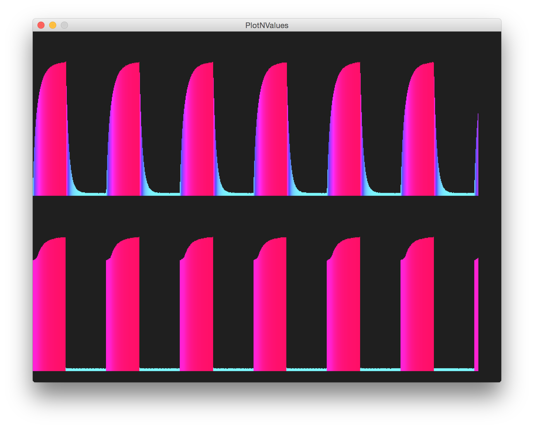
Here are some sample traces of the resulting waveforms as measured by the Arduino with various values of 𝛕 for the RC integrator. The lower trace is the square wave at pin 3 of the 555 timer, the upper trace is the triangular wave at the output of the RC integrator:
A very close match to the theoretical best fit

Close alternative using single standard component values in the RC integrator.
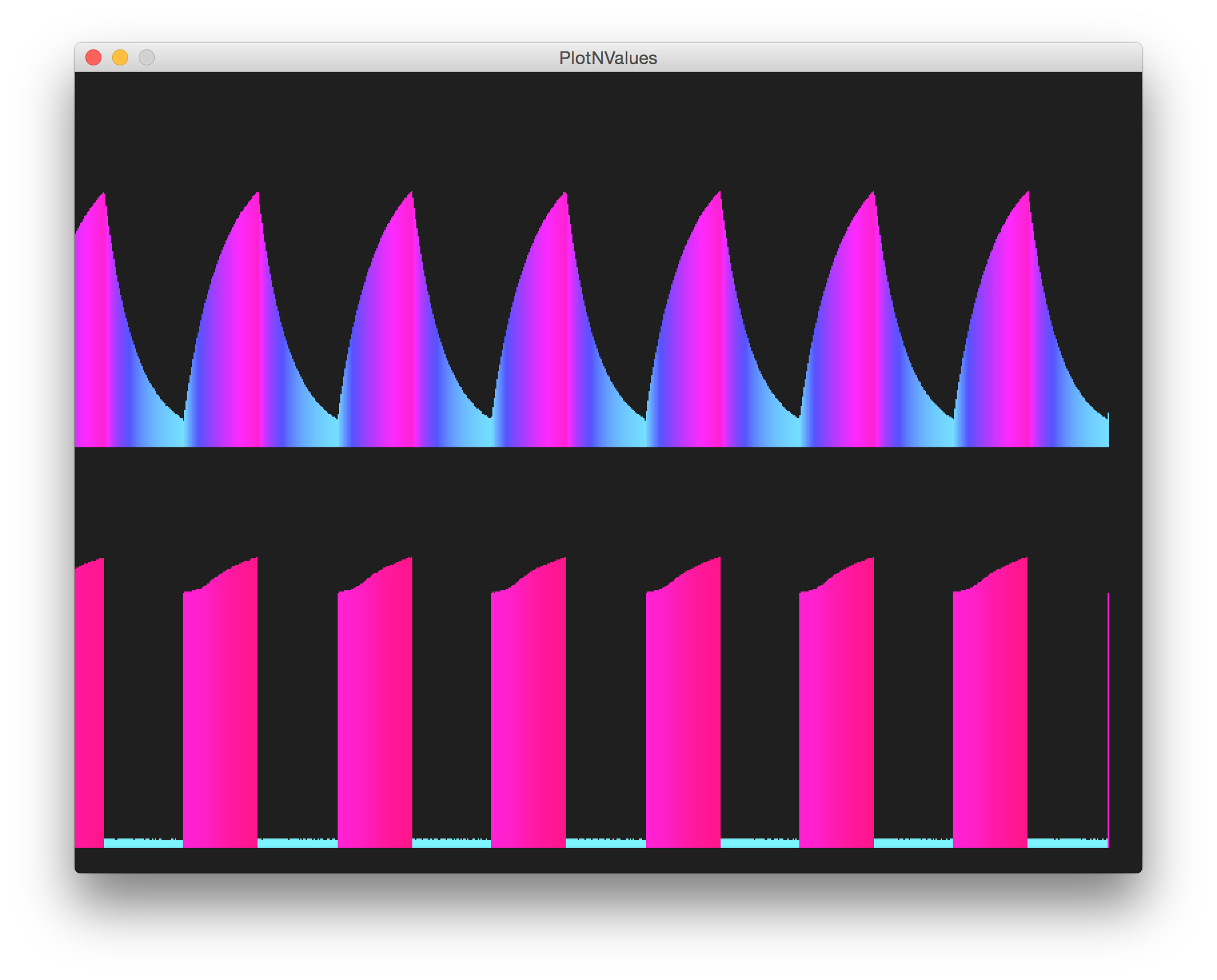
With 𝛕 too high, significant DC offset builds up in the capacitor. But notice a very nice triangle!

With 𝛕 too low, the charge/discharge cycle falls well within the square wave periodicity.
The Arduino only acts as a measurement device in this circuit.
LEAP#090 PlotNValues (a simple Processing sketch) reads the data from the serial port and plots the input and output value over time, with some coloration effects thrown in for good measure. In other words, we're using Arduino and Processing as a basic oscilloscope! And it kind of works, mainly because the frequency is so low.


NB: the schematic describes the circuit being driven from the Arduino 5V pin. That works fine, although the build picture shows the 555/RC integrator being driven using a separate 5V breadboard power supply. That also works fine! (It's just important to ensure there is a common ground connection).