Observatory Automation with LesveDomeNet
The LesveDomeNet dome control is based on a USB I/O controller, 2 relays, an azimuth sensor and a home position switch.
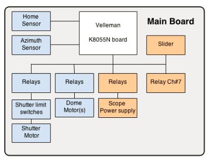
TBD - When I figure things out I will replace the following architecture overview image (taken from) the LesevDom main page with a drawing of my own, something that is specific to my setup.
Reference
- Ed Plumer's Modification to LesveDome
- Charles Harrow Schema
- This page provides some details of Morning Star's efforts in automating his Exploradome using the LesveDome system
-
For help download the LesveDomeNet chm doc file. Before you can view it you must right-click->properties and select unlock. Here is a pdf version of the help
-
LeveDomeNet_Readme.txt
LesveDomeNet is installed as an ASCOM dome in the  directory

C:\Program Files (x86)\Common Files\ASCOM\Dome\ASCOM.LesveDomeNet

The following files will work in the background, they have no visible application windows

  ASCOM.LesveDomeNet.exe          the local server
  ASCOM.LesveDomeNet.Dome.dll     the dome driver
  ASCOM.LesveDomeNet.Switch.dll   the switch driver
  K80XX_Driver.dll                a utility file for the local server
  K8055D.dll                      the K8055 driver provided by Velleman

A Graphical User Interface application to access the LesveDomeNet driver

  ASCOM.LesveDomeNet.UserInterface.exe
I plan to use the ELK relays as shown in Ed Plumer's blog post
Below are my various attempts and revisions on the electronic schema for my setup:

This illustration is taken from my Dome Automation Deck


Based on Ed Plumer's Schema

Adapted from Ed Plumer Schema
K8055N Connection Schema
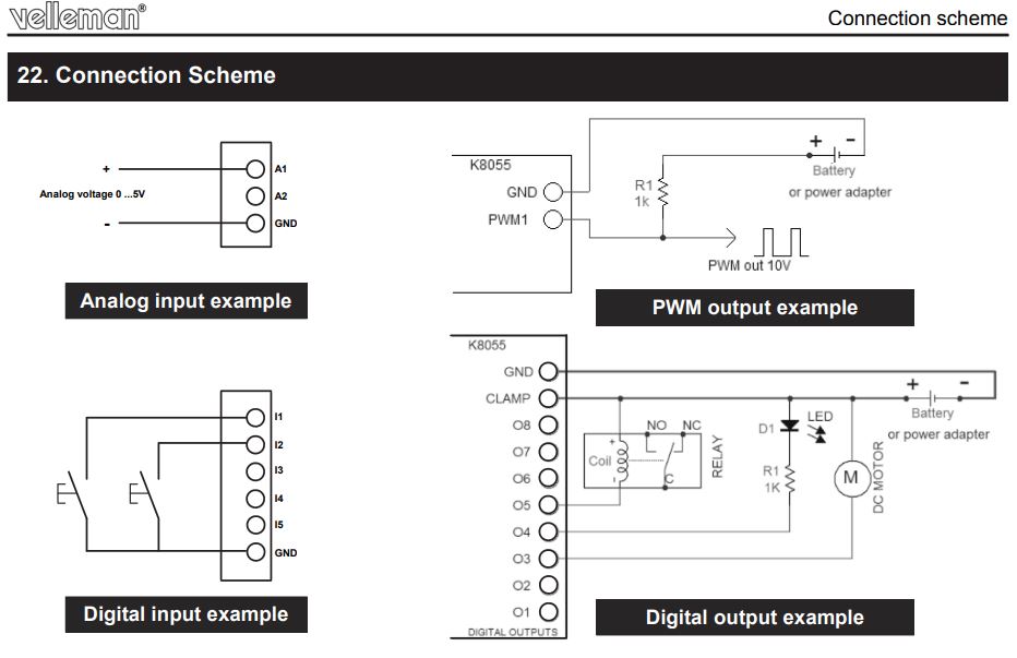
Taken from the illustrated user manual
-
Velleman K8055N Usb Experiment Interface Board
- Order 2/10/2018 - Amazon Order Number: 114-5722661-4746627
- Velleman VM110N Usb Interface Card Module - this is the same as the K8055N but comes assembled!
Digital Input Channels
- Input-1 - Azimuth Sensor “CCW motion”
- Input-2 - Home position switch
- Input-3 - Scope turned on bit
- Input-4 - Dome Motor direction
- Input-5 - Azimuth Sensor “CW motion”
Digital Output Channels
- Output-1 - Dome Motor ON/OFF
- Output-2 - Dome Motor direction CW CCW
- Output-3 - Scope On - controlled by "Switch" driver as Switch #1
- Output-4 - Scope Off - controlled by "Switch" driver as Switch #1
- Output-5 - Shutter Motor ON/OFF
- Output-6 - Shutter Open/Close. Open when relay is active
- Output-7 - Ch#7 auxiliary relay - controlled by "Switch" driver as Switch #3
- Output-8 - Dead Man Switch
More detail about inputs and outputs can be found in the Lesve Doc on page 15.
Note: Only the bold I/O channels noted above are used in my application.
I plan to use the ELK relays as shown in Ed Plumer's blog post.
- ELK-912 Relay - Single switch used to control dome motor on/off
- ELK-924 Relay - Two switches used to control dome Motor direction CW CCW
I am using the following encoder and cable for my azimuth sensor:
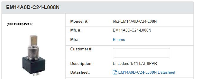
- EM14A0D-C24-L008N Encoders 1/4"FLAT 8PPR
- 652-H-290-2 Ribbon Cables / IDC Cables EM 14 Cable
- Ordered on 3/42018 from Mouser (Order Number: 13726326) Reference
- DIY azimuth sensor information is on the LesveDomeNet site
- see msg in yahoo group on this topic
-
Velleman HAA27 Reed Switch
- Order 2/10/2018 - Amazon Order Number: 114-3425971-1235442
The dome drive system is made up of a motor with a driver sprocket that is connected by chain to a driven sprocket attached to a caster wheel. The dome is resting on three caster wheels so that when one turns the dome will rotate. The following picture illustrates the setup:
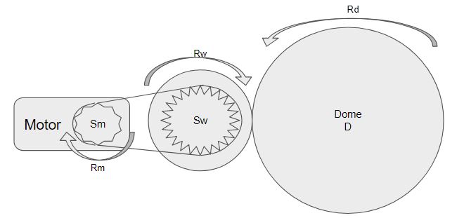
This illustration is taken from my Dome Automation Deck
- Sm - Sprocket attached to motor drive shaft, 9 Teeth
- Sw - Sprocket attached to 5” caster wheel used to drive the dome, 25 teeth
- D - The observatory dome, 11.5 ft diameter
- Rm - Rotation of motor drive shaft
- Rw - Rotation of drive wheel
- Rd - Rotation of dome
Below shows how to compute the ratio of Rm to Rd so dome speed can be computed given a certain motor speed.
The rotation ratio of the sprocket on the motor (Sm)
to the sprocket on the wheel (Sw)
Given: Sm - 9 teeth, Sw - 25 teeth ()

       driven      Rw      25
       ------  =  ---- =  ----
       driver      Rm      9

       For each 25 turns of the motor the caster wheel turns 9 times

 The rotation ratio between the wheel and the dome
 Given: As seen by observation; The wheel turns 27 times
        for each complete spin of the dome

       driven      Rd      27
       ------  =  ---- =  ----
       driver      Rw      1

       For each 27 turns of the wheel the dome turns once


Combine the two ratios

       driven      Rd      25     27     675     75
       ------  =  ---- =  ---- * ---- = ----- = ---- = 75
       driver      Rm      9      1       9       1

       For each 75 turns of the motor to dome turns once

Compute Dome RPM using Rd:Rm from above
and at 12 Volts the measured motor speed is 10.5 RPM
Given the dome is larger we divide

        Dome RPM = (10.5 / 75)
                 = 0.14 RPM

       The dome rotates about a tenth of a turn every minute

Final - Dome RPM = 0.14 RPM
      - it will take about 7 min to turn once
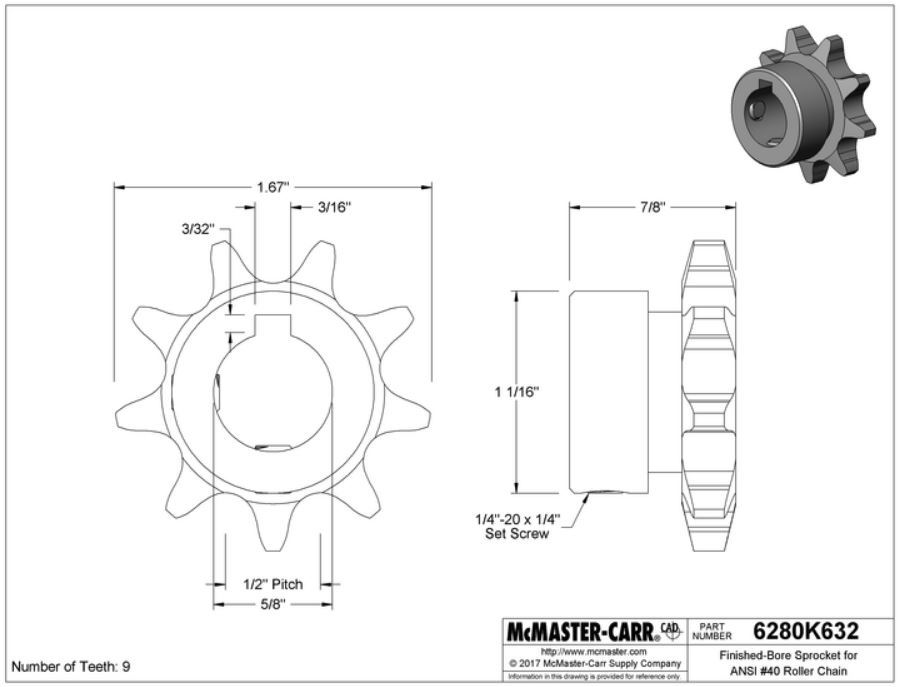
Motor Sprocket (Sm)
The sprocket that came with the motor will not work with a bike chain so I am going to get the following from McMasters-Carr:
Caster Wheel Sprocket (Sw)
The guy over at Wheeliefunbikes.com gave me an old bike sprock from his parts pile. So I think the following is correct:
- Number of teeth: 25
- Old bike part
- Fits ANSI #40 with 1/2 in pitch (this is what I believe a bike chain to be)
Motor
Looking to repurpose a use motor:
| Attribute | Value |
|---|---|
| Type | 24A4BEPM-3F |
| Volts | 130 AC or DC? |
| HZ: | DC, FF 1.0 |
| A | 0.48 |
| HP | 1/17 |
| Ratio | 5.1 |
| RPM | 500 |
| Torq | 5.2 lb-in |
- specs plate image taken from the side of the motor
- full image of the motor
Reference
- Related CN post: Dome rotation what motor size do I need?
- Motor alternatives if things don't workout:
- There is some useful information about how powerful your motor needs to be in this link. http://www.geckodrive.com/support/choosing-a-drive.html
- motor sprocket
- 10 tooth sprocket search
- Circuit Simulators
- electronic circuit simulator - the one that lets you "see" the current
- circut lab - on line simulator
- LTspice is a high performance SPICE simulator,
- List of Circuit design / analysis / simulation software
- Wires:
- I believe for the PBC I will be using
solid 20 gauge (0.32mm) hookup wire - In this video he is using
solid 30 gauge (0.25mm) rework wire - see: AWG chart for sizes
- I believe for the PBC I will be using
- How to solder grid style PCB
- Lessons in Electric Circuits
- How to meter check a diode