A PWM charge-pump approach for driving low-current 0V, 5V, 12V output levels from an Arduino GPIO pin.

Here's a quick demo..
For some microcontroller projects, especially those involving chip programming for older devices, it is necessary to apply higher-than-normal voltages on specific pins (for an EEPROM erase, for example). Usually only very low current/power is required.
How to do that with a nominally 5V microcontroller? This project outlines one approach, I'm sure there may be improvements or alternatives. It involves:
- a PWM-controlled Dickson Charge Pump to generate a higher voltage (12V in this case) than the microcontroller power rail (5V)
- high-side p-channel MOSFET switching of the high voltage to the intended output
- BJT switching to enabled a "normal" high voltage of 5V, or a hard pull-down to 0V.
The net result is a 3-level output voltage (0V, 5V, 12V), using 4 GPIO from an Arduino.
- 2 pins are actually used to drive the PWM charge pump - pins D3, D11 using Timer2 for PSM generation. These would not be required if a separate 12V supply or boost converter was used.
- 1 pin (D4 in the example sketch) acts as the "high voltage" enable/disable
- 1 pin (D5 in the example sketch) acts as the output high/low selector
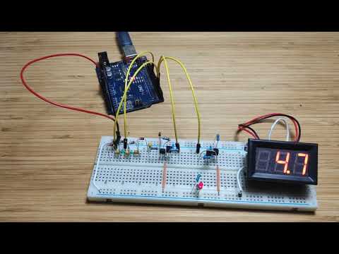
I tested the circuit on a breadboard:


I've added a voltage display unit to measure the actual output voltage (to within a few 10's of mV):
The test script MultiVoltageGPIO.ino exercises the circuit: it switches from 0V to 5V to 12V output on a loop, with each output change every 1 second.
To capture a scope trace of the output (below), I switched to a 100ms transition delay, and plotted the output with a -5V offset:

