
⚠️ CAUTION: This project involves working with electrical components and may require handling of high voltage connections. Always prioritize safety, use proper insulation, and consult with a qualified electrician if you're unsure about any aspect of the installation or operation.
📢 Development Notice: This project will no longer receive feature updates. A new NodeMCU 12E (ESP8266) version: Smart Aquarium V3.1 is ready & ESP32 version: Smart Aquarium V4.0 is under development that supports more powerful customization options and advanced monitoring features for aquarium inhabitants. Be the first ones to try it out and give feedbacks! 🚀
- 🌐 Web-based control interface
- ⏰ Automated timing controls
- 🌡️ Real-time temperature monitoring
- 💡 Smart lighting control
- 🔄 Power-saving modes
- 📱 Mobile-responsive design
- 🔄 OTA (Over-The-Air) updates
- ⚡ Low latency control
| Component | Image | Purpose |
|---|---|---|
| NodeMCU ESP8266 |  |
Main controller with WiFi capabilities |
| DS3231 RTC Module |  |
Accurate time keeping |
| OLED Display | 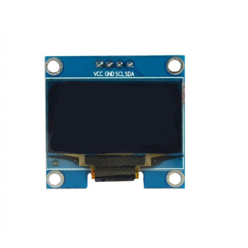 |
Status display |
| 4-Channel Relay |  |
Control aquarium equipment |
# Clone this repository
git clone https://github.com/desifish/Smart-Aquarium-V2.0.git

# Navigate to the directory
cd Smart-Aquarium-V2.0

# Open in Arduino IDE
# Update WiFi credentials in aqua_NODEMCU.ino
# Flash to NodeMCUImportant: The favicon image inside the
datafolder needs to be copied into the flash storage of the NodeMCU. This ensures the web interface can properly display the favicon. For instructions on how to upload files to the ESP8266 filesystem using LittleFS, please refer to this updated guide.
📌 Version History
- v1.12 - Added Power Saver Mode
- v1.11 - Updated UI with customizable timers
- v1.10 - Added auto-start relay feature
- v1.9 - Added web-based time updates
- v1.8 - Added Auto/Manual Control
🔌 Wiring Diagram
NodeMCU ESP8266 -> OLED Display
D1 -> SCL
D2 -> SDA
3.3V -> VCC
GND -> GND

NodeMCU ESP8266 -> DS3231
D1 -> SCL
D2 -> SDA
3.3V -> VCC
GND -> GND

NodeMCU ESP8266 -> 4 Channel Relay
D3 -> IN1
D5 -> IN2
D6 -> IN3
D7 -> IN4
5V -> VCC
GND -> GND
The full schematics for this project are available in PDF format: View/Download Schematics
Quick Reference
Note: For detailed connections and component values, please refer to the PDF schematics.

Key Components:
- NodeMCU ESP8266 (Main Controller)
- DS3231 RTC Module
- OLED Display (128x64 I2C)
- 4-Channel Relay Module
- Power Supply (5V)

Safety Features:
- Isolation between mains and low voltage
- Proper grounding connections
- Fuse protection
The system provides an intuitive web interface accessible from any device on your network:
- 💻 Desktop View
- 📱 Mobile-Responsive
- 🎛️ Real-time Controls
- 📊 Status Monitoring

This project is licensed under GPL-3.0 License - see the LICENSE file for details.
License Details
Permissions:
- ✅ Commercial use
- ✅ Modification
- ✅ Distribution
- ✅ Patent use
- ✅ Private use
Conditions:
- 📝 License and copyright notice
- 📄 State changes
- 📦 Disclose source
- 📜 Same license
Limitations:
- ❌ Liability
- ❌ Warranty
Made with ❤️ for the IoT Community
