Hardware Description
The Libre Solar BMS is divided into two different boards:
- Control board (BMS48V)
- Power board (Switch-N-Sense)
A picture of the current version is shown below:
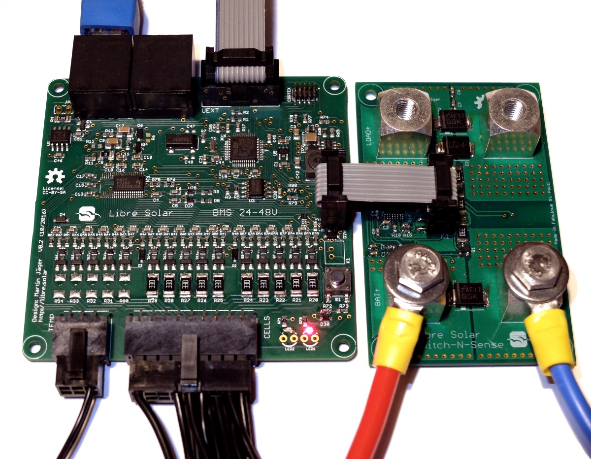
On the bottom of the control board (left side), the cells are connected for balancing and voltage monitoring. In addition to that, up to three temperature sensors (10k thermistors) can be connected to the board. The board features a CAN interface through two daisy-chained RJ-45 connectors. Via the universal UEXT connector, additional peripherals can be connected via SPI, I2C or USART.
The Switch-N-Sense board acts as the interface between the Li-ion battery and the outside world. It contains the sense resistors for current measurement and charge/discharge MOSFETs at the bottom side. For improved cooling, it can be attached to a cooling plate. The wire-to-board connection is done via Würth Power Element press-fit connectors, allowing very high currents.
The two boards are separated in order to adjust the power part depending on your actual needs. If you only need to deliver low currents from the battery, the Switch-N-Sense board can be smaller and cheaper.
This repository contains only the control board. Please see the Switch-N-Sense repository for details on the power part of the BMS including hardware files.
For cell supervision, balancing and main safety features, the BQ76930/BQ76940 analog front-ends from Texas Instruments are used. The board layout can be used for the 10s and the 15s version of the chip family, but not for the 5s version.
On the picture above, the 10s IC (bq76930) is used, so the balancing resistors for the top 11-15 cells were not populated.
The board is equipped with a push-button which boots up the system. Boot-up of the bq769x0 is achieved by applying a voltage >1V to the TS1 (thermistor 1) pin. After boot-up of the bq769x0, its internal LDO supplies 3.3V to the enable pin of the LMR16006X switch-mode power supply which provides power to the 5V rail. The 5V rail is directly connected to the CAN transceiver. The STM32F072 microcontroller is supplied by an addtional LDO to generate 3.3V. (the internal LDO of the BMS IC is not used due to its very low power output).
Shut-down is done via software from the MCU. The MCU will monitor a long press of the push-button via the BTN signal and put the bq769x0 IC to sleep mode after 3s. During sleep mode, the internal LDO will stop working and and also shut down the switching power supply for the rest of the system. In this mode, the BMS will only drain some micro-amps from the battery and is essentially dead.
Instead of the push-button, a switch connected to the board via the connector K1 can be used for remote on/off switching.
Please make sure that all temperature sensors are connected or bridged with a 10k resistor. Otherwise the system will not boot up and work properly.
This interface is intended to be used for a future communication protocol between different devices of a small renewable energy system. The software for the high-level CAN protocol is still to be developed.
A small 256 bytes EEPROM can be used to store settings (like cut-off voltages, etc.) of the BMS.
This standardized connector can be used to extend the board with custom hardware like displays, wireless connection etc. A large variety of available modules can be found at Olimex.
The BMS contains a real-time clock. In addition to that, future generations will probably get a native USB connection.