Inconsistent values when using "analogRead()" #92
Comments
|
I did not go into depths with measuring the result, but I have seen similar results on the ESP31B. As far as the code goes, there isn't much that can be changed :) we ask the hardware to measure the level on given channel, and it returns the value to us. I have made sure that pins are properly initialized and all possible pulls have been disabled. |
|
Many thanks for the prompt answer. Now that you mention it I think I saw some thread on the official forum talking about different levels on ADC initialization and internal voltage references and some guy also complaining about poor results. I think it was related to test version of ESP31 so I kind of hoped these issues were addressed. I have got the feeling if I want accurate results I am going to head for a dedicated ADC IC :( |
|
That guy complaining was probably me :) |
|
Lol btw you are making a great work on this Arduino port ;-) This is just me being a little bit pushy but any idea of when can we expect analogWrite? |
|
I'm waiting for the last PWM driver to be documented and prepped in IDF. There are currently 3 options that you can use for PWM already available.
//SigmaDelta Setup(pin 16, channel 0)
sdSetup(0, 10000);//channel, frequency
sdAttachPin(16, 0);//pin, channel
//SigmaDelta Write
sdWrite(0, 128);//channel, 8bit value

//LEDC Setup(pin 17, channel 5)
ledcSetup(5, 10000, 16);//channel, frequency, bits
ledcAttachPin(17, 5);//pin, channel
//LEDC Write
ledcWrite(5, 1024);//channel, bits value

//DAC (pins 25 or 26)
sdWrite(25, 128);//pin, 8bit value
sdWrite(26, 65);//pin, 8bit value |
|
OK, that explains my confusion last weekend :-) My tests also showed 4095 for 3.3V and 0 for 0V |
|
if someone has a digital potentiometer, maybe we can make up the logic behind ADC reads |
Do you get better results if you use lower resistor values (ie 1K or 470 ohm)? There will be some internal impedance to the ADC when it takes a sample (I don't actually know how much but can find out). ~4.7K input impedance may be enough to pull the measured voltages down slightly.. Another way to test this theory is to put a small capacitor between the ADC pin and ground, the extra capacitance should prevent the voltage from drooping when the ADC samples from a high impedance source like the resistor divider. EDIT: This theory doesn't really explain the TMP36 result @hcs-svn mentions, as the sensor has a low impedance output already - unless there's a resistor between the sensor output and the ADC pin. |
|
I have just connected the output of the voltage divider to a high precision opamp (LMC6482) used as a buffer to eliminate any kind of error. Ouput of the buffer is clean at 2.462V which should be around 3070 but ADC still reads a value close to 2785, even less than before :( I doubled check the ouput of 3V3 pin and is giving 3.286V so the error is still quite huge, close to 10% according to my tests. Hope we can get some light here Update: My initial test was using GPIO35. |
|
The ADC frontend indeed has a non-linear response. Once characterization data is ready, we will take it into account inside ADC APIs, and update the datasheet with correct values of INL/DNL and effective resolution. |
|
Privet @igrr , |
|
This is critical for me, due to a temperature sensing application. I'm wishing to port from Particle Photon P1, though not being able to analog read accurately would be a show stopper. Very keen to hear if this has been fixed.. ? |
|
Like @markterrill I also am looking to do temperature sensing applications with the ESP32. So I'm assuming the addition of broken in idf label means not much can be done? From the ESP32 page (https://www.esp32.com/viewtopic.php?t=1045 ) it seems like they were going to add something to the firmware to make this better. It also looks like using a lower attenuation (-6db) and using a range of 0.1v - 1.8v will get you mostly linear results. I have yet to test this however. @bobik78 - It means if the input voltage is 3v3 (which it is) then your hi range for the 11db is 3.3 and not 3.9 as its rated. I agree...its a little confusing. Personally I've found it a little lower then that in practice, anything about 3.2ish pegs it at 4095. |
|
@copercini - "Broken in idf" means no software fix? As a followup I cannot get a NodeMCU ESP32-s board to take the commands to change the read width nor the attenuation: https://esp32.com/viewtopic.php?f=19&t=2881&sid=fdffa84f0fd6047bb6a588d2baf6dcdc . It seems to just ignore the commands even though it compiles and uploads fine from my sketch. Does this also not work? And if so how do I make my attenuation 6db instead of 11db since 11 is so noisy? |
|
@vseven it just means that is no problem in the Arduino layer (this repository) but the solution needs to come from IDF first to be implemented here This issue was open before attenuation workaround, maybe now some examples how to use it in Arduino will be great! Please make a PR if you get any progress :D Edit: you are redeclaring the funcions in your code of esp32 forum, please take a look at this post https://esp32.com/viewtopic.php?f=19&t=2881#p13712 it show the correct calling of adc functions |
|
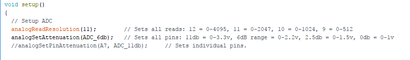
@vseven Try these: analogReadResolution(12); //12 bits
analogSetAttenuation(ADC_0db); //For all pins
analogSetPinAttenuation(A18, ADC_0db); //0db attenuation on pin A18
analogSetPinAttenuation(A19, ADC_2_5db); //2.5db attenuation on pin A19
analogSetPinAttenuation(A6, ADC_6db); //6db attenuation on pin A6
analogSetPinAttenuation(A7, ADC_11db); //11db attenuation on pin A7 |
|
Thank-you @copercini - the problem was I was trying to call them outside of a function, which failed, which I then was declaring them thinking that would work (lack of knowledge on my part). I moved the statements in your example to within my setup() and now it's compiling. I haven't tested it yet but I'm assuming it will work. Side note: Something else that was confusing me...the Arduino IDE shows analogReadResolution in red but analogSetAttenuation in black so I thought I was typing something wrong. Is this normal?
|
|
The orange thing is because the arduino IDE have a list of "known functions", like AnalogReadResolution and AnalogRead. The "analogSetAttenuation" isn't in that list since it is a function that only works on ESP32. But there are some tricks to set "analogSetAttenuation" as orange too. Don't worry about it, it's just a visual thing. Your code comments are really nice, if you make an example with this stuff will help a lot of people! fell free to make a PR |
|
I'll see what I can do about examples but as you can tell I'm a little inexperienced. 10+ years of VB.Net programming makes this stuff look like Greek to me. Oh...my results in case anyone cares: https://esp32.com/viewtopic.php?f=19&t=2881&p=13739#p13739 |
|
awesome work. thanks. |
|
Hey there, it looks like idf now contains a calibration method: espressif/esp-idf#164 (comment) Does that fix this issue? I am thinking about getting some esp32s.. |
|
Hi, inesp32wemos lolin oled , I can only use the GPIO36 and GPIO39 when i use wifi, the others porst reading bad values!!!!!! |
|
@Morgan679 : ADC2 is not available while WiFi is running (https://docs.espressif.com/projects/esp-idf/en/latest/api-reference/peripherals/adc.html#overview). ADC1 is pins 32-39. |
|
This issue has been automatically marked as stale because it has not had recent activity. It will be closed if no further activity occurs. Thank you for your contributions. |
|
Maybe you should test: |
|
And it easy to calibrate your own ESP32 |
|
Calibration is now included in the esp-idf which uses a lookup table combined with factory calibration values (in newer chips). #1804 (comment) |
|
Good to know. I have an old one. |
|
[STALE_SET] This issue has been automatically marked as stale because it has not had recent activity. It will be closed in 14 days if no further activity occurs. Thank you for your contributions. |
|
[STALE_DEL] This stale issue has been automatically closed. Thank you for your contributions. |
Hi,
I checked yesterday the new implementation of analogRead and values are pretty incosistent. Not sure if it is because of the implementation of the method or just because the ADC on ESP32 is not very accurate.
I created a simple several stage voltage divider to read on. Source was the 3.3V output pin of the ESP WROOM 32. Then I applied 3 different steps with 4.7K 1% tolerance resistors. Values measured with the multimeter:
P1: 3.286V --> Expected = 4095 / ADC output = 4095
P2: 2.462V --> Expected = 3071 / ADC output = 2811
P3: 1.641V --> Expected = 2047 / ADC output = 1814
P4: 0.819V --> Expected = 1021 / ADC output = 823
Any explanation to this? I though the levels would go from 0 being 0V and 4095 being top of the range 3.3V
I need to rely on an accurante ADC for my project so any help is welcomed. Cheers!
The text was updated successfully, but these errors were encountered: