I wrote this guide to give step by step instructions on how to make your own controller input display (currently the same setup as siglemic). This setup currently works with NES, SNES, N64, and GCN controllers. You can check out what the final product looks like in some of cylon13's or my video history.
- Arduino Uno. You might be able to find this cheaper elsewhere. A clone such as Funduino works just as well.
- USB cable to connect the Arduino to your computer
- controller extension cable (NES, SNES, N64, or GCN)
- (optional) male/female connectors with 5 pins minimum for easy controller switching
- wires to solder into the controller extension cable to go to the Arduino (the Arduino sockets are very small, so you will need some smaller gauge wire to fit, so it might be best to pickup some wire after you see the socket size)
- wire cutters/strippers
- exacto knife or box cutters
- soldering iron and solder
- electrical tape
- digital multimeter or a cheap continuity tester
- the latest Arduino software
- firmware to program into the Arduino with
- PC software to connect to the Arduino and display the controller
#2 and #3 above are included in the release package of NintendoSpy. The firmware is located in the firmware folder and is called firmware.ino. Just run NintendoSpy.exe to launch the display software.
This is the most time consuming piece, especially if you have never done any wiring/soldering before.
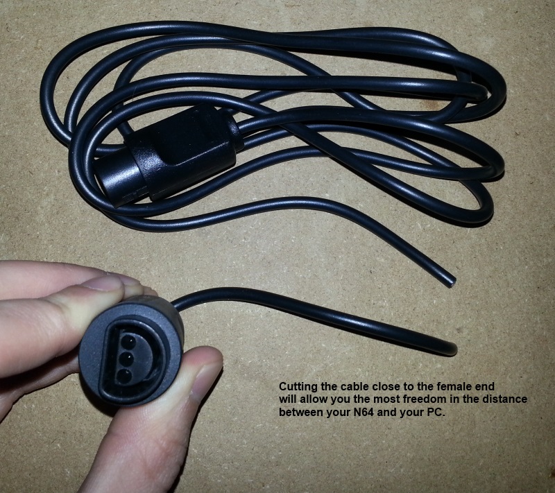
- First you will need to cut your controller extension cable so you can splice into the wires (consider which spot in the extension cable to cut, game system side, controller side, middle)
-
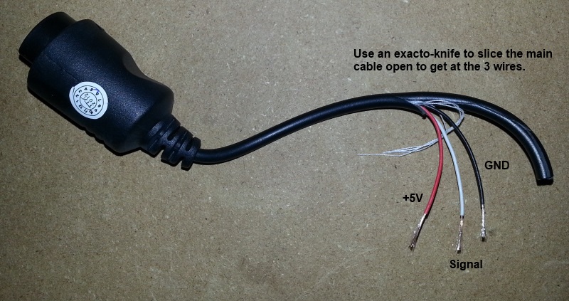
Use your exacto knife or box cutters to very carefully cut away and peel back the plastic covering on both halves, about 2-3 inches should be good enough.
-
Use wire strippers to strip back about 1/2 an inch of the plastic covering on each wire. In my case I had to carefully use my exacto knife because the wires were too small for the stripper, I rotated the wire against the blade until I could pull the plastic off the end.
-
Next you will need to use a digital multimeter or continuity tester to figure out which pin on your controller plugin goes to which wire in the extension cable, make sure to write down your findings. A quick google search of " + controller pinout" should give you the information you need.
-
Here are the minimum pins we are interested in for each system:
- NES - Latch, Data, and Clock
- SNES - Latch, Data, and Clock
- N64 - Data and Ground (there are only 3 wires, so it's pretty obvious here)
- GCN - Data and (any non-shield)Ground
-
Figure out the length you need between your controller extension cable/Arduino and cut and strip a wire for each wire you are going to splice into.
-
Solder each wire back together with your spliced wires, here's what mine looked like when finished I soldered them this way (instead of end-to-end) because this will provide more strain relief against the small controller extension wires possibly breaking with use.

-
After soldering everything back together, test out your extension cable with your game system to see that it still works before proceeding.
-
Use electrical tape to tape up each wire separately.

- Again use electrical tape to tape all the wires back together, make sure to tape all the way back up to where the extension cable covering starts

-
(optional) Wire the spliced cables to a connector to make easy swapping between controllers, you will need the opposite gender connector, pins, and more wires to go to the Arduino.
-
Hook up the newly spliced extension cable to your Arduino according to this pinout.
Note I am using a breadboard here to just jumper the wires over to the Arduino, it is not needed.


Once the wiring is done, hook everything up to your game system and computer, now for the easy part.
-
Plug in the USB connector to your Arduino and PC.
-
Install the latest Arduino software, download the Windows Installer option.
-
Once installed, open the Arduino software, you should see "Arduino Uno on COMX" at the bottom right corner if everything is working. If not, you may need to restart and/or replug the USB connector.
-
Download and unzip the latest release of NintendoSpy somewhere.

-
Select File->Open and open the
firmware.inofile from the firmware folder of the unzipped NintendoSpy release. -
Now uncomment the option for the operation mode (which controller) you will use. Note I am using a SNES controller here.

- Hit the upload button (right pointing arrow) located just under the 'Edit' menu, this will upload and run the software on the Arduino. It should look like the following image. Once successfully uploaded, you won't have to upload software again to the Arduino again unless you want to change controller modes.

-
Run
NintendoSpy.exe. -
The selection here should be pretty straightforward, select the 'COMX' port that the Arduino is on, select the controller you are using, select a skin, and hit 'Go'. If everything is hooked up correctly you should see your controller and inputs displaying.
-
Celebrate with a cold drink and a playthrough of your favorite game :>
I found that the N64 display will not work correctly if you have a memory pack plugged into the controller. I haven't tested, but possibly the rumble pack could do this as well. The latest version of NintendoSpy has a "blink reduction" mode which compensates for the firmware's unreliability in certain cases. If you are having problems with inputs "blinking", right click the view window and select "Blink Reduction".
-
The most common problem is likely to be wiring, so if the input display isn't working I would double check that a) The controller is working with your game system. b) The correct pins are wired between your extension harness to the correct pins on your Arduino. c) Your PC can see your Arduino on a COM port (you are able to upload the firmware.ino to your Arduino)
-
If you are having trouble getting the Arduino programming software working or getting it to see your Auduino on a COM port, try the guide located at
C:/Program Files (x86)/Arduino/reference/Guide_Windows.html.
Send a message to either cylon13 or StarkNebula on Twitch for details on getting one built.
There are no plans for any seriously new features at the moment, but this repository is always open for bug fixes and new skins. If you create skins feel free to submit them as pull requests to this repository, or file an issue. You can submit issues if you find any problems with the software as well.
Why do you need an Arduino board for this to work? Can't you just use the split extension cable and wire the other end into a USB adapter for the PC?
These controllers require 2-way communication to work properly. For example, this means that a SNES sends data to the controller as well as the controller sending data back to the SNES. If you plugged in both the SNES and the USB adapter to a PC there would be (in effect) 2 SNES systems trying to talk with a single controller, and nothing would work properly. The reason that the Arduino works is that it merely 'listens' to the data going back and forth between the system and controller, it does no communication itself.
If you have any other questions about this setup, feel free to post issues to this github repository, contact me on my Twitch channel or on SRL IRC under the same nick, or contact cylon13 on twitch.