laser module TTL vs PWM #13
Comments
|
last thing is the first laser module doesn't have the board, it's directly connected to the controler board laseraxe. |
|
Here's the response from AliExpress shop gktools. Yeaaaaah China!
|
|
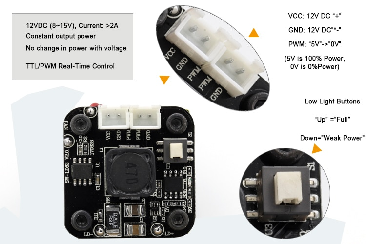
Connector changed from 2p2p to 3p. C Careful to the poles...I didn't had special connetors. ^^
Match poles from controller. 12V/GND/PWM
|


|
Still a problem with eleksmaker and chinese Arduino + laserweb. What is this ArduinoClone? usb chip CH340x Bon, Bsod, j'ai perdu ma doc sur le fabmob10. https://www.pihomeserver.fr/en/2018/02/17/raspberry-pi-gravage-laser-cnc-eleksmaker-a3-pro/ |
|
rapidement
check EEprom setings via "$$"
"120","X-axis acceleration","mm/sec^2","X-axis acceleration. Used for motion planning to not exceed motor torque and lose steps."
"100","X-axis travel resolution","step/mm","X-axis travel resolution in steps per millimeter." actual |

note concernant elekslaser little sebastian16 Octobre
En soit, l'écart n'est pas si grave et j'ai même agrandit. Pour éviter les tensions dans les matériaux.
LA coupe du profilé alu était le coupable. Lorsqu'on serre, le plexi se plaque contre la coupe et se déforme un peu. Ce qui crée tension et désalignement.
ça devrait être bien là. Vive la colle chaude.
Done
Ressource tuto assemblage. pour le futur. Et planche de travail pour en dessous.
côté logiciel,
Donc 80 steps/mm à configurer via les commandes |


Reste
Solution temporaire,
|

|
Bug de moteur qui ne sont pas mis sous tension. |
I also got the two lasers (3pin and 4pin - Version). I want to get it up and running without an external board. I have followed these instructions (https://www.instructables.com/id/Laser-Engraving-on-Your-Prusa-MK3/), but this does not work, nor does the connection of a simple power source and the subsequent removal does not turn off the laser. Only disconnecting the power source switches it off again. |
|
Ok, waw that's quite a hack. @satblip that could be interesting on the prusa :) Logically, if the laser is controlled by using the same command as for the fan, using the yellow wire (TTL)
And I actually made this error because I didn't had the right connector and at some point I remember to put red wire on VCC but I changed cable (needed different length) and cables red/yellow was inverted and I put 12V on the TTL 5V. And I burned a capacitor. Anyway, back to your problem. |
|
Ohh, you missunderstand me. Sorry. My question: This revealed the following phenomenon: Now I want to use the PWM signal, so I have, as described in the instructions, connected the cable and let the fan rotate. The laser is still fully on. If I deactivate the fan, the laser dims slowly, but then switches back to 100%. It seems to me that the laser processes the PWM signal, but as soon as there is no current at the TTL / PWM pin, the laser automatically switches to 100% (I will probably have to investigate this further) I also tested to apply 5V to the TTL / PWM pin and then connect the 12V to turn on the laser. This too was unsuccessful. Turning off the 5V left the laser on. I did the same test with a simple 5V power source. Here, no change in the brightness of the laser was recognizable, since this is just 5V (100% brightness) or 0V (unfortunately, 100% brightness). After all this was unsuccessful, I ordered a second laser. Now the 4 pin version. Here was a similar phenomenon, which is why I can almost rule out a technical error on the laser almost. But so far I have no approach to finding a solution. I hope someone can help, because a certain despair spreads at home currently. At the supplier / dealer, I am unfortunately unaware of, as this itself apparently has no idea regarding the problem. |
|
Mmmm, right. From what I learned from building, using and repairing the lasersaur, (100W CO2) Which could explain why on your module, it turn ON when fan OFF because maybe it need a High TTL signal to actually turn OFF the laser....
Yes, don't forget about the PWM/TLL signal, it should be a constant voltage but with a modulation of frequency. It pulse. |
|
Really nice hack to keep on the idea board for the future indeed! thx @Depio ! |
|
Hi nicolasdb. |
|
Other thing. I trying to use with an arduino uno, mana board. |
|
I'm not in the lab for a couple of weeks but I saw something engraved on the main body, it was mentionned if the laser was analog or digital. The one I just solder a 3P connector instead of 2P2P worked perfectly (except I burn it afterward by inverting PWM and VCC ^^' |
|
With all certainty. I almost got tested. My luck is I saw before calling, because the signal on the oscilloscope was strange. If you put 12VDC on the TTL / PWM pin of this controller, it burns in the act. |
|
Hi, I'm attempting to run the prusa mk3 laser engraver hack, but I'm a bit confused. I can't get the laser to power on (anything other then the dim test button) with the fan ttl connection. My question is - for the 3-pin vcc/ground/ttl lasers, does the ttl get connected to the prusa fan's yellow line or the red line? (i've tested w/ red power line and cant' get it to work:( asking before I take everything apart again..) Thanks |
|
I got it working, for others that may search here, it is indeed the red fan line not the yellow. The important part was adding a 1k resister between ground and ttl on the laser itself.. (I had initially added a 4.7k resistor which didn't work..) |
|
Hi diomark. |
|
And i'm not using the driver that came with my laser. I'm controlling for pwm. |
|
oldshark - i'm using this one - https://www.banggood.com/EleksMaker-FB03-500-500mW-Blue-Laser-Module-2_54-3P-TTLPWM-Modulation-for-DIY-Laser-Engraver-p-1266178.html?rmmds=myorder&cur_warehouse=CN seems to work fine, although to be honest so far I've only tested it on cardboard and paper. |
|
The driver is the same, my LD is 2.5w. |
|
I just ordered that one too just to play with.. -m
…On Tue, Jan 29, 2019 at 2:31 PM OldShark ***@***.***> wrote:
The driver is the same, my LD is 2.5w.
—
You are receiving this because you commented.
Reply to this email directly, view it on GitHub
<#13 (comment)>,
or mute the thread
<https://github.com/notifications/unsubscribe-auth/ATqrBdMGmgGy11ombzGNR996qiU4FE-4ks5vIMuqgaJpZM4W81Id>
.
|
|
This year I want to buy a 15w. |
|
Where u from? Here is Brasil, São Paulo |
|
bonjour, |


|
tu peux donner un peu plus de détails? |
|
La verte c'est là où mon Lazer et brancher directement dessus. |
|
ok, donc carte noire = controleur, carte verte = driver laser. à celà: Il est tjs conseiller de suivre aussi les polarités +- si c'est mentionné sur la carte. |


|
Je viens d'effectuer les branchements que vous venez de me conseiller, j'ai
lancé une gravure et le laser ne s'allume pas
Le mer. 13 mars 2019 à 13:48, Nicolas de Barquin <notifications@github.com>
a écrit :
… ok, donc carte noire = controleur, carte verte = driver laser.
en toute logique, la puissance est fournie alors par le driver. donc le
controleur ne doit envoyer que de l'info TTL/PWM en 5V.
Donc, je pense que tu dois connecter ceci:
[image: image]
<https://user-images.githubusercontent.com/12049360/54279898-79a86200-4596-11e9-8cdc-e2ae283ca96e.png>
à celà:
[image: image]
<https://user-images.githubusercontent.com/12049360/54279924-89c04180-4596-11e9-81be-5fd081da6c9f.png>
Il est tjs conseiller de suivre aussi les polarités +- si c'est mentionné
sur la carte.
—
You are receiving this because you commented.
Reply to this email directly, view it on GitHub
<#13 (comment)>,
or mute the thread
<https://github.com/notifications/unsubscribe-auth/AuMsXo2WUqFCCu-_ydJUIE0FqEgXC1NSks5vWPOKgaJpZM4W81Id>
.
|
|
Bonjour Djorimar et Nicolasdb. |
|
Le français est bon merci. oui je pense aussi . Parque quand j'ai acheté la
carte il y avez écrit .Oui j'ai un multimètre .
"Nouvelles fonctionnalités de la version v0.9 :
Le Baud Rate en série par défaut est désormais de 115 200. (au lieu de
9600)
L'entrée limite de l'axe Z en D11 a été échangée avec une broche permettant
à D12 de prendre en charge une sortie variable de PWM.
Pas de file d'attente : La file d'attente a été retirée car elle est
devenue redondante. La mise en attente met en pause Grbl et n'autorise que
les commandes en temps réel. Le début du cycle reprend, et réinitialise les
sorties.
Nouvel algorithme par étapes fluide : Refonte complète de la manipulation
du pilote d'étapes pour simplifier et réduire le temps de tâche par timing
d'ISR.
Mises à jour de la stabilité et la robustesse.
Planification 4x plus rapide.
Vitesse de rotation de sortie variable.
Compilable via Arduino IDE.
Refonde de l'analyseur syntaxique de la programmation de commande
numérique : Entièrement réécrit pour une conformité totale à la
programmation de commande numérique standard.
Paramètres d'accélération et de vitesse indépendants.
Limites douces : Vérifie si chaque commande de mouvement dépasse les
limites de l'espace de travail avant de l'exécuter, et déclenche une alarme
en cas de franchissement d'un seuil.
Sonde : Les commandes de programmation numérique standard de sondes des
G38.2, G38.3, G38.4 , Et G38.5 sont désormais prises en charge et
connectées via la broche A5.
Décalages de la longueur des outils.
Performances Arc améliorées.
Nouveau simulateur Grbl : Un wrapper complètement indépendant du code
source principal de Grbl qui peut être compilé en un exécutable sur un
ordinateur. Pas besoin d'Arduino. Il simule les réponses de Grbl comme s'il
était sur un Arduino. Cartographie des broches du CPU.
Rapports d'état configurables en temps réel.
Retour à la position initiale mis à jour : Positionne le volume de l'espace
de travail dans un espace négatif, quelle que soit la position limite de
retour.
Contenu :
1 x Carte mère CNC keyestudio
1 câble USB
Détails & caractéristiques
- Il s'agit d'une carte mère de machine à commande numérique conçue pour
divers projets DIY et utilisation en usine
- Réalisez des projets de gravure au laser, de robots d’écriture et de
dessin de machines Oddball, etc.
- Dispose de toutes les interfaces nécessaires pour un prix raisonnable,
peut-être connectée à un disque dur externe
- microprocesseur : MEGA328P / tension d'entrée : 12 V CC/prend en
charge les formats de fichier : Gcode
- Scannez le code QR sur l'image pour obtenir le tutoriel d’explication,
le schéma de câblage, et comment installer des logiciels et tester la
planche
Le mer. 13 mars 2019 à 17:03, OldShark <notifications@github.com> a écrit :
… Bonjour Djorimar et Nicolasdb.
Pardon pour ingérence et pour mon pauvre Français.
Nicolas D'après ce que je comprends, vous utilisez un contrôleur
keyestudio, est-ce tout?
Je pense qu'il a déjà une sortie pour contrôler le laser par PWM, mais je
ne sais pas quelle est la tension, mais d'après ce que je vois devrait être
12V même. Dans ce cas, vous devrez le connecter à un pilote laser, tel que
la carte verte.
Certaines choses Quelle est la tension de fonctionnement de votre laser?
Avez-vous un multimètre?
—
You are receiving this because you commented.
Reply to this email directly, view it on GitHub
<#13 (comment)>,
or mute the thread
<https://github.com/notifications/unsubscribe-auth/AuMsXgwVDxUE5tRJvpyVpkatxxBS-ksfks5vWSFNgaJpZM4W81Id>
.
|
|
Parfait, mais j'aimerais vraiment savoir quel est le problème. Je pensais que j'essayais de connecter la sortie du keyestudio à ce pilote laser. Je ne sais pas si cela fonctionnerait. Cette sortie laser de keyestudio doit être une MLI, car j’ai vu qu’elle pouvait aussi commander un moteur à courant continu. |
|
Mon problème c'est que je voudrais faire du nuances de gris.
Le mar. 12 mars 2019 à 12:56, Nicolas de Barquin <notifications@github.com>
a écrit :
… tu peux donner un peu plus de détails?
t'as 2 cartes controleurs? la verte c'est quoi? le driver?
—
You are receiving this because you commented.
Reply to this email directly, view it on GitHub
<#13 (comment)>,
or mute the thread
<https://github.com/notifications/unsubscribe-auth/AuMsXt7DsWSeUz0CVevdygXA0nwWbKpJks5vV5XygaJpZM4W81Id>
.
|
|
J'ai compris. Et avec cette plaque photo vous ne pouvez pas? |
|
En fait, TTL et PWM seront en niveaux de gris. L'un se fera par modulation d'impulsion et l'autre par intensité laser. Je l'utilise par PWM. Le pilote de mon laser étant gravé (TTL), je l’ai fait en utilisant PWM avec la broche 7 d’Arduino. Je fais varier l'intensité du laser, variant ainsi le degré de combustion du matériau. |
|
Help!!!! I'm new to laser engraving, I bought a 5.5w laser with ttl and mounted it on my anycubic i3 mega i connected the fan cable to the ttl and power to independent 12v supply. The ttl did not work at all. Then I connected the fan cable to the 12v input on the laser. It modulated the laser for a brief moment then turned off completely. Can any one suggest what's going wrong? Thanks |
Hello kdm. |
|
Here is the link to the board on my printer. https://rover.ebay.com/rover/0/0/0?mpre=https%3A%2F%2Fwww.ebay.com%2Fulk%2Fitm%2F302581784739 |
|
Hi Kdm.
The problem I see with using your 3D is not having access to the board firmware. And where u from? Cause u from Brazil, more simple to help u. See this video. |

|
Hi I am in the UK. I will try the led trick. The fan must be pwm as you can directly control the fan speed from the 3d printer when it's printing. I have tested the fan cable on a multimeter and it reads 12v unconnected but as soon as I plug it into either the 12v or ttl port on the laser module it drops to 2.7v. It's very frustrating. Hope you can help. |
|
Oh My Gosh! I´m have the same problem with my laser module. And i thinking i had burned my driver. LoL. Using a mosfet n to control then power by TTL. In my case i only remove the laser driver and wire mosfet pwm to laser direct. My TTL pulse Teste whit the LED and multimeter or oscilloscope. |


|
I still can't figure out why this DDP crash when connecting to the driver. and your case is exactly like mine, it drops to 50% of the voltage. If I'm not mistaken I commented here on Git, but no one could help me. This led me to use this solution. Test there and let's keep in touch. After all you are the first person I know with exactly the same problem as me. I don't even know if your driver is this. |
|
I have done some more research on the board on my printer. And your thought on the fan not being pwm was correct. Apparently you can turn on soft pwm in marlin firmware but I'm hesitant to do this in case I mess things up. It's annoying as I replace my old printer with this one as the other nearly caught fire. And that one did have pwm. I was planning on building a cnc frame with arduino driver in the near future so think I will have to focus on that for it to work properly. |
|
Got it. The problem is, I don't see any TTL ports on your card really. But if it uses Marlin as firmware, it must be ATMega based. Surely there must be some lost TTL pin. Ideally an oscilloscope to figure it out. |
|
hi. can you help me please choose correct board.. let me explain my situation... |
|
Hi sklymenko. |
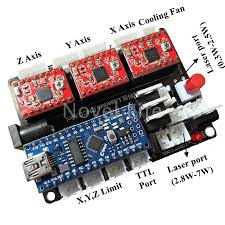
Ok, Houston, we have a problem.
I order a second minilaser diode for fabmob but I was not please with the first one and I order the same used by bemaker this time. The machine is arrived, it's mounted but the laser module is lost somewhere.
Hopefully, I bought earlier another laser module as safety parts.
and because it's never easy and never work on the first attempt, connectors don't fit.
It's same same as the first (I was thinking)

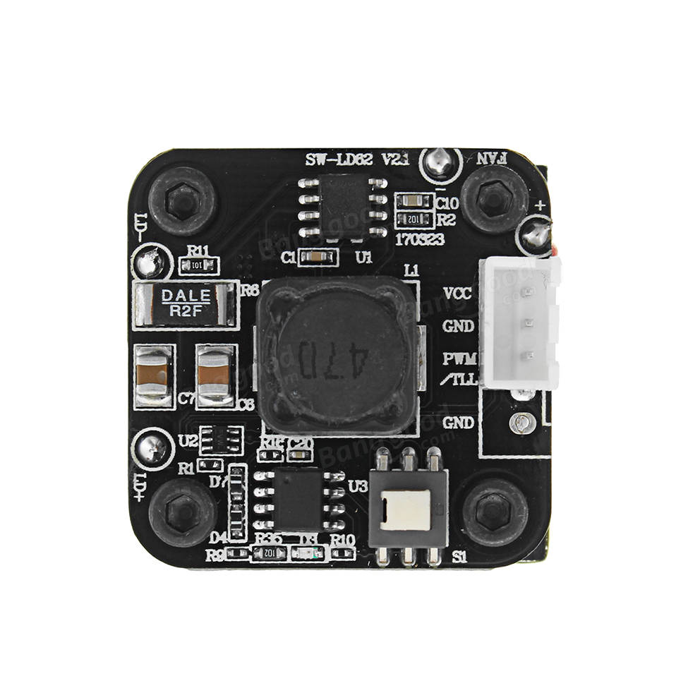
But with Eleksmaker, it's a 3pin cable for the same module but like this.

The control board is the "SW-LD62 v2"

And I found this part.
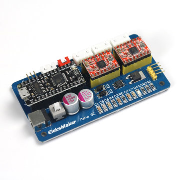
Eleksmaker use the mana board controler.

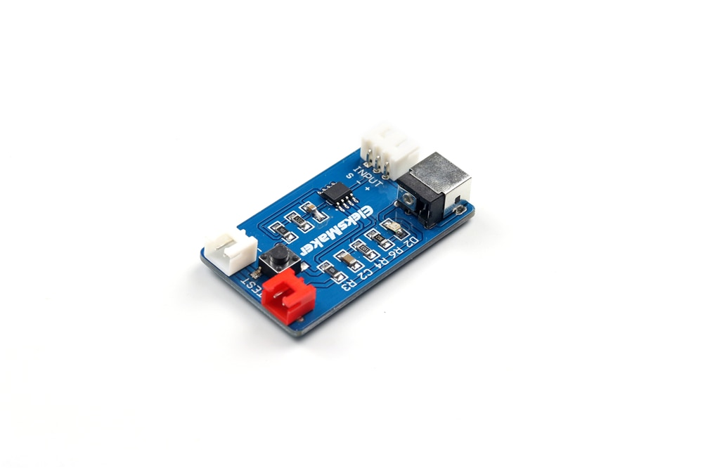
The other is laseraxes board.

Seems less good than the other. And the power supply connector is a bit loose, it doesn't match the size of the power supply (2.5mm vs 2.1mm probably, tssss)
But have 2 place to connect laser, depending of the laser power. both 2pins.
note: I have a second mana board... ^^So my question is simply, "what about unsolder 2pin connector and solder 3pin connect instead?" Right?
The text was updated successfully, but these errors were encountered: