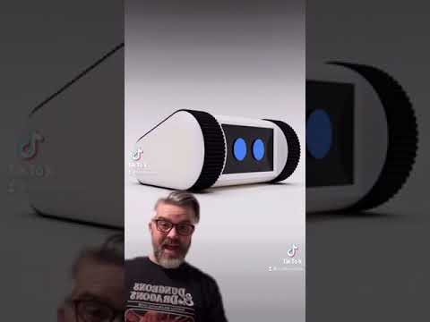
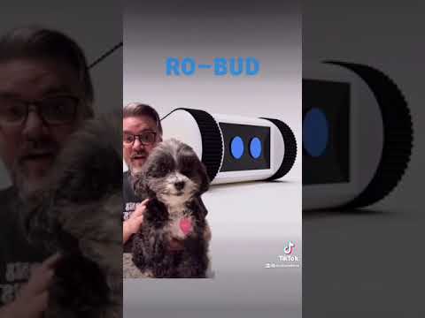
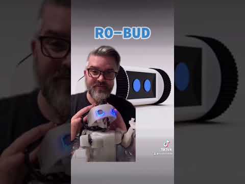
The Ro-Bud project seeks to create a companion bot that is lovable, accessible to all, and autonomous.
Challenge: Despite decades of fictional depiction through popular culture, as of 2021, robotic companion bots that even come close to those of popular imagination are not available at scale.
While there have been impressive private for-profit attempts at releasing relatively advanced consumer companion bots, specifically Jibo and Anki Vector, these endeavors ultimately proved commercially unviable, forcing the companies to fold, and effectively removing these wonderfully engineered robots from either availability or full operability (as they were dependent on proprietary services provided by their now-defunct companies).
The Ro-Bud project is an attempt to pick up where Jibo and Ankni left off, and fulfil the dream of providing a consumer robot that is:
- LOVEABLE - Feels just like a family pet
- ACCESSIBLE - Can be built by anyone following project instructions with readily available parts with a cost at or under $500
- AUTONOMOUS - Has it's own goals.
NOTE: The following build instructions are in-progress and not yet complete
Last updated 17-August 2022

Documentation To-Do
- Add 3d-printable models
- Jetson Wifi Module Install
- SD Card Flashing
- Head Assembly
- Remote VM setup
- Remote Operation Instructions
- A. horizontal braces stl
- B. 3-hole fastener stl
- C. 2x8mm round-head self-tapping screws https://www.amazon.com/gp/product/B07NT5288W
- D. 2x8mm pan-head-with-washer self-tapping screws https://www.amazon.com/gp/product/B07NTGRFBF
- E. BNO055 orientation sensor https://www.adafruit.com/product/4646, https://www.digikey.com/en/products/detail/adafruit-industries-llc/4646/12609996
- F. SainSmart IMX219 Camera Module https://www.amazon.com/gp/product/B07VFFRX4C
- G. VL53L0X time-of-flight distance sensor https://www.adafruit.com/product/3317
- H. 1-hole 2mm screw fastener stl
- I. 300mm 15-pin camera ribbon cable https://www.adafruit.com/product/1648
- J. 100mm Stemma QT JST SH 4-pin cable https://www.adafruit.com/product/4210
- K. display fastener stl
- L. servo adapter stl
- M. head barrel wall stl
- N. head shaft adapter stl
- O. bearing https://www.amazon.com/gp/product/B07S1B3MS6
- Q. MG90S 9G micro servo https://www.amazon.com/gp/product/B07F7VJQL5
- R. ~~5in display https://www.adafruit.com/product/1678, https://www.digikey.com/en/products/detail/adafruit-industries-llc/1678/10670051
- S. ~~40 Pin Flexible Flat Ribbon Cable 0.5mm Pitch - 200mm https://www.amazon.com/gp/product/B07C4P6S43
- T. mono enclosed speaker - 3W 4 Ohm https://www.adafruit.com/product/3351
- U. head L bracket stl
- V. servo horn (included with servo(Q))
- W. servo screw (included with servo(Q))
- CC. SparkFun Qwiic SHIM for Raspberry Pi https://www.sparkfun.com/products/15794
- DD. Stacking Header for Pi A+/B+/Pi 2/Pi 3 - 2x20 Extra Tall Header https://www.adafruit.com/product/1979
- EE. Adafruit DC & Stepper Motor Bonnet for Raspberry Pi https://www.adafruit.com/product/4280
- FF. Break-away 0.1" male header https://www.adafruit.com/product/392
- GG. Male/Male Jumper Wires - 20 x 6" (150mm) https://www.adafruit.com/product/1957
- HH. Female/Female Jumper Wires - 20 x 6" (150mm)Female/Female Jumper Wires - 20 x 6" (150mm)
- II. Heat shrink tubing https://www.adafruit.com/product/1649
- JJ. 3.5mm (1/8") Stereo Audio Plug Terminal Block https://www.adafruit.com/product/2790
- KK. Rocker toggle switch (comes with chassis kit)
- LL. Servo Tester https://www.amazon.com/gp/product/B07TQSKLBK
- MM. PCA9685 16 Channel 12 Bit PWM Servo Driver https://www.amazon.com/gp/product/B07RMTN4NZ
- NN. Baseus Power Bank, 65W 20000mAh Laptop Portable Charger https://www.amazon.com/gp/product/B08THCNNCS
- OO. x2 USB-A Male Plug to 5-pin Terminal Block https://www.amazon.com/gp/product/B07H53X194 (2-pack), https://www.digikey.com/en/products/detail/adafruit-industries-llc/3628/7931507 (1-pack)
- PP. x2 Stacking Header for Pi https://www.adafruit.com/product/1979, https://www.digikey.com/en/products/detail/adafruit-industries-llc/1979/6238003, https://www.amazon.com/gp/product/B071XCHZNB/(4 pack)
- QQ. M2.5 brass stand-off kit https://www.amazon.com/gp/product/B075K3QBMX/ (or equivalent)
- RR. 22AWG Silicone Hook Up Wire (stranded) https://www.amazon.com/gp/product/B07T4SYVYG/ (or equivalent, you want not-too-stiff wire than can handle 4 amps)
- SS. STEMMA QT / Qwiic JST SH 4-Pin Cable - 400mm long https://www.adafruit.com/product/5385, https://www.digikey.com/en/products/detail/adafruit-industries-llc/5385/16546436
- TT. Heat Shrink Tubing https://www.amazon.com/gp/product/B01MFA3OFA (can be subbed with electrical tape, or equivalent)
- UU. 5.0" 40-pin 800x480 TFT Display without Touchscreen https://www.adafruit.com/product/1680
- VV. TFP401 HDMI/DVI Decoder to 40-Pin TTL Breakout - Without Touch https://www.adafruit.com/product/2218
- WW. 40-pin FPC Extension Board + 200mm Cable https://www.adafruit.com/product/2098


Full list of Head Assembly Parts
-
3d Printed Parts (Ender 3 settings - PLA, Raft recommended, defaults otherwise)
-
Adafruit (recommend sourcing from DigiKey for best US price/shipping)
- x1 E. BNO055 orientation sensor https://www.adafruit.com/product/4646, https://www.digikey.com/en/products/detail/adafruit-industries-llc/4646/12609996 (often out of stock due to chip shortage. Check DigiKey, Adafruit, Mouser & Amazon)
- x1 G. VL53L0X time-of-flight distance sensor https://www.adafruit.com/product/3317, https://www.digikey.com/en/products/detail/adafruit-industries-llc/3317/6569762
- x1 I. 300mm 15-pin camera ribbon cable https://www.adafruit.com/product/1648, https://www.digikey.com/en/products/detail/adafruit-industries-llc/1648/7035020
- x1 J. 100mm Stemma QT JST SH 4-pin cable https://www.adafruit.com/product/4210, https://www.digikey.com/en/products/detail/adafruit-industries-llc/4210/10230021
- ~~x1 R. 5in display https://www.adafruit.com/product/1678
- x1 T. mono enclosed speaker - 3W 4 Ohm https://www.adafruit.com/product/3351
-
Amazon
- x7 C. 2x8mm round-head self-tapping screws https://www.amazon.com/gp/product/B07NT5288W
- x20 D. 2x8mm pan-head-with-washer self-tapping screws https://www.amazon.com/gp/product/B07NTGRFBF
- x1 F. SainSmart IMX219 Camera Module https://www.amazon.com/gp/product/B07VFFRX4C
- x1 O. bearing https://www.amazon.com/gp/product/B07S1B3MS6
- x1 Q. MG90S 9G micro servo https://www.amazon.com/gp/product/B07F7VJQL5
- x1 ~~S. 40 Pin Flexible Flat Ribbon Cable 0.5mm Pitch - 200mm https://www.amazon.com/gp/product/B07C4P6S43
- x1 V. servo horn (packaged with Q MG90S 9G micro servo)
- x1 W. server screw (packaged with Q MG90S 9G micro servo)
- x1 LL. Servo Tester https://www.amazon.com/gp/product/B07TQSKLBK
- x1 MM. PCA9685 16 Channel 12 Bit PWM Servo Driver https://www.amazon.com/gp/product/B07RMTN4NZ
- x1 UU. 5.0" 40-pin 800x480 TFT Display without Touchscreen https://www.adafruit.com/product/1680
- x1 VV. TFP401 HDMI/DVI Decoder to 40-Pin TTL Breakout - Without Touch https://www.adafruit.com/product/2218
- x1 WW. 40-pin FPC Extension Board + 200mm Cable https://www.adafruit.com/product/2098
Parts:
- x2 A. horizontal braces
- x1 B. 3-hole fastener
- x3 C. 2x8mm round-head self-tapping screws
- x4 D. 2x8mm pan-head-with-washer self-tapping screws
- x1 E. BNO055 orientation sensor
Notes:
- Make sure Y axis of BNO055(E) points toward picture as shown in image
- Only fasten one side of the horizontal braces(E)

Parts:
- x1 F. SainSmart IMX219 Camera Module
- x2 C. 2x8mm round-head self-tapping screws

Parts:
- x2 H. 1-hole 2mm screw fastener
- x2 C. 2x8mm round-head self-tapping screws
- x1 G. VL53L0X time-of-flight distance sensor


Parts:
- x1 I. 300mm 15-pin camera ribbon cable
- x1 J. 100mm Stemma QT JST SH 4-pin cable
Notes:
- Make sure pins of ribbon cable are facing toward contacts and fastened securely
- Attatch STEMMA QT cable(J) securely to right STEMMA sockets on VL53L0X(G) and BNO055(E)

Parts:
- x1 M. head barrel wall
- x1 L. servo adapter
- x2 K. display fastener
- x4 D. 2x8mm pan-head-with-washer self-tapping screws
Notes:
- Make sure fasteners and raised center lip are on opposite sides
- Make sure slotted sides of the display fasteners(K) are face up, with open sides pointed inside the circle, and closed ends are pointed out
- Make sure servo adapter is oriented as shown in image
- If servo adapter cannot be popped in, soften with a hair dryer or heat gun


Parts:
- x1 Q. MG90S 9G micro servo
- x1 LL. Servo Tester
Parts:
- x1 Q. MG90S 9G micro servo
- x2 M. left barrel wall(M) from step 5
Notes:
- Body of servo should be on same side as fasteners from step 5

Parts:
- x1 N. head shaft adapter
- x1 O. bearing
Notes:
- If shaft cannot be popped in, soften with a hair dryer or heat gun
- The longer side of the shaft should be in the bearing

Parts:
- x1 M. head barrel wall
- x2 K. display fastener
Notes:
- Make sure fasteners and raised center lip are on opposite sides *Balance weights shown in photo are no-longer used. Please ignore

Parts:
- x1 bearing(O) with shaft(N) from step 8
- x1 right barrel wall(M) from step 9
Notes:
- Make sure shaft is on the opposite side of the clips & weights
- If bearing cannot be popped in, soften with a hair dryer or heat gun

Parts:
- x2 A. horizontal braces
- x2 B. 3-hole fasteners
Notes:
- Make sure to add 3-hole fastener(B) to both sides

Parts:
- x1 Left barrel wall with servo (from step 7)
- x1 Lower horizontal head brace (from step 11)
- x2 D. 2x8mm pan-head-with-washer self-tapping screws


Parts:
- x1 Left barrel wall with servo (from step 12)
- x1 Top horizontal head brace with camera (from step 1)
- x2 D. 2x8mm pan-head-with-washer self-tapping screws


Parts:
- x1 R. 7in display
- x1 S. 250mm 40pin display ribbon cable
Notes:
- Make sure pins of ribbon cable are facing toward contacts and fastened securely

Parts:
- x1 R. 7in display
- x1 left barrel wall with servo (from step 12)
Notes:
- Make sure the cables are on the bottom (opposite camera) and feed bewtween both horizontal braces

Parts:
- x1 right barrel wall(M) with bearing and shaft (from step 10)
- x2 D. 2x8mm pan-head-with-washer self-tapping screws

Parts:
- x1 T. mono enclosed speaker - 3W 4 ohm
- x2 D. 2x8mm pan-head-with-washer self-tapping screws

Parts:
- x1 U. head L bracket
Notes:
- If shaft does not pop onto L bracket, use hair dryer or heat gun to soften

Parts:
- x1 U. head L bracket
- x1 V. servo horn
- x1 D. 2x8mm pan-head-with-washer self-tapping screw


Parts:
- x1 W. server screw
Notes:
- IMPORTANT: The servo horn should be pointing straight down attached with screen pointing straight left
- Be careful not to turn servo shaft when attaching. If you do, repeat step 6.


These videos are the original annoucement and project plan for Ro-Bud uploaded to TikTok on 17-April 2021.