-
Notifications
You must be signed in to change notification settings - Fork 8
Raspberry PI bare metal
License
tuxyme/metal-pi
This commit does not belong to any branch on this repository, and may belong to a fork outside of the repository.
Folders and files
| Name | Name | Last commit message | Last commit date | |
|---|---|---|---|---|
Repository files navigation
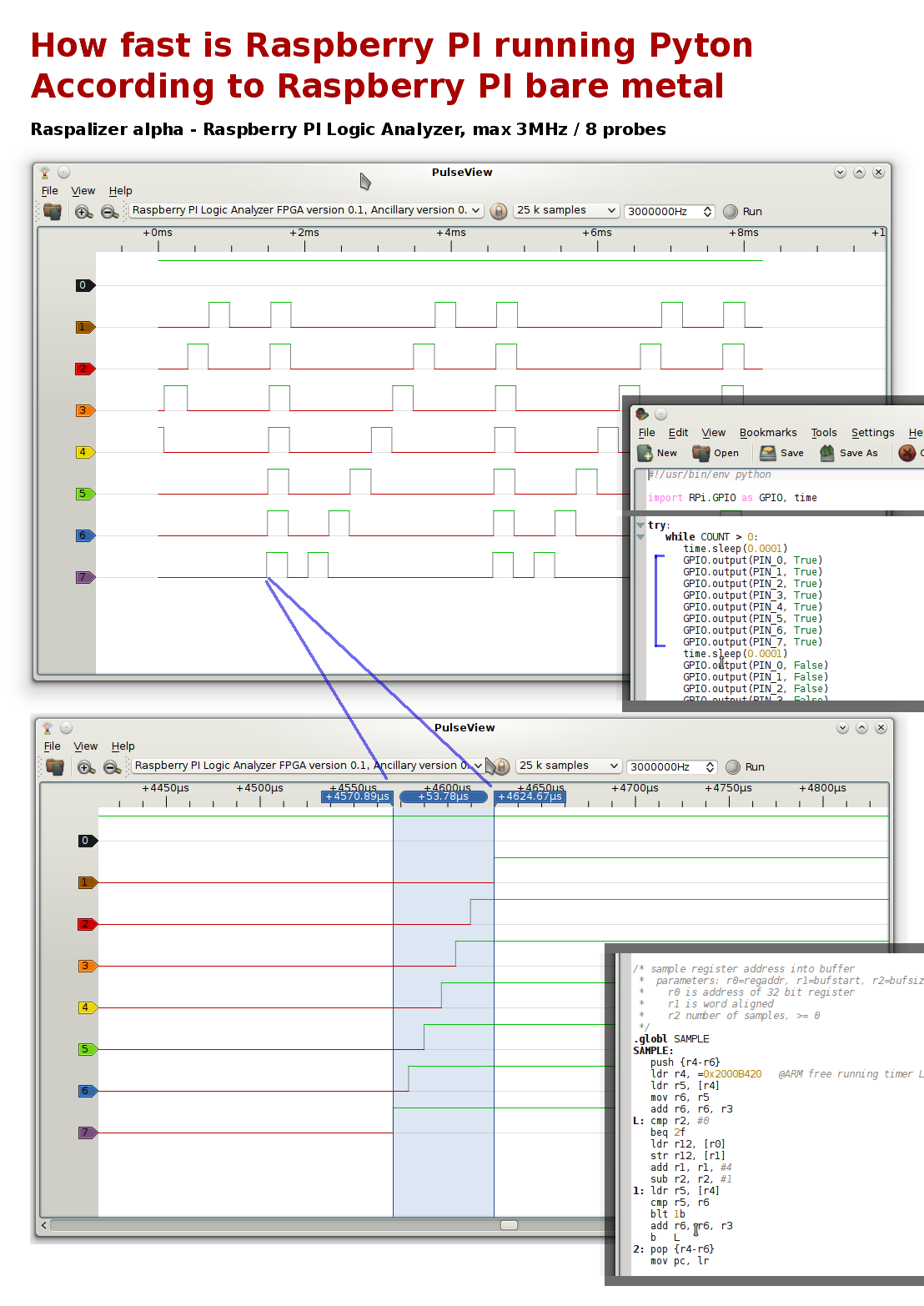
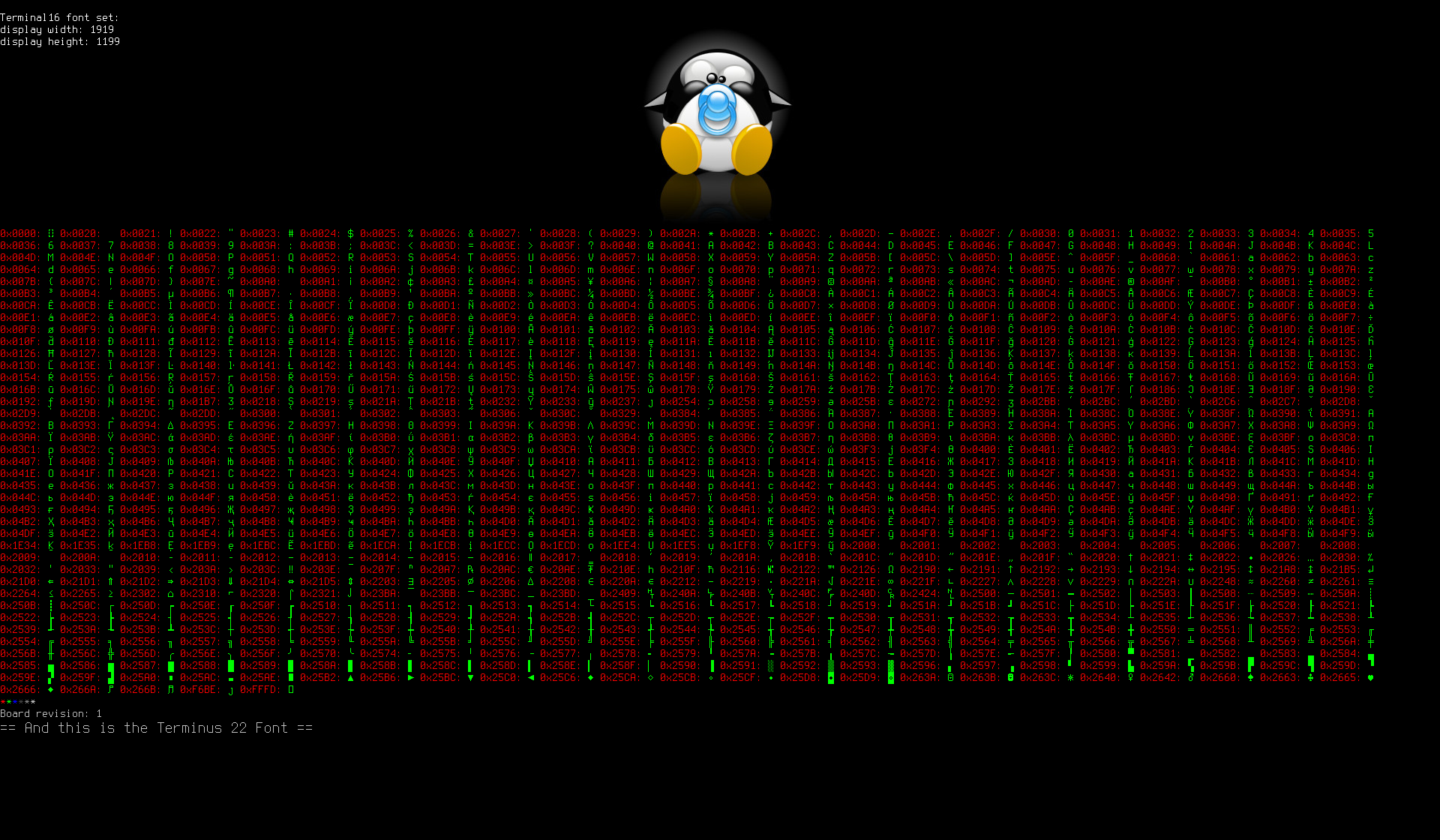
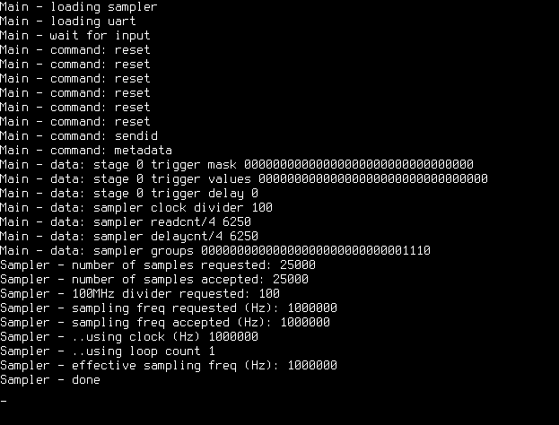
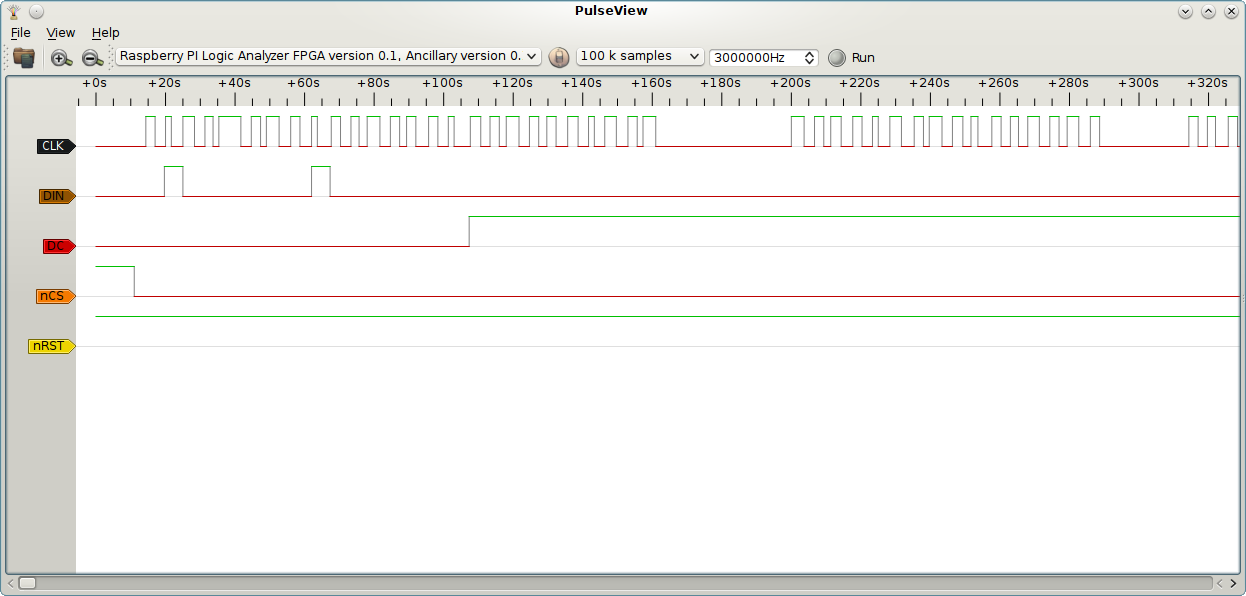
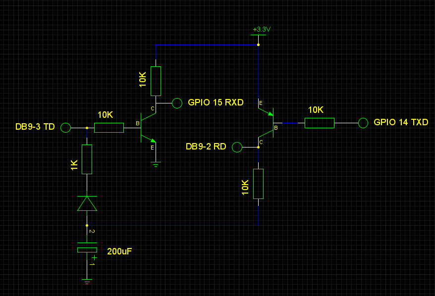
Raspberry PI Logic Analyzer
===========================
This is a bare metal project I started for fun. And to shake off a couple of
years of Java and get back to C again. The result is a Raspberry PI Logic
Sniffer and Analyzer to be.

Features:
- max samplerate 3 MHz
- max 16 probes
- compatible with sigrok
- talks to sigrok via serial connection

Now these features relate to the sniffer part of an analyzer and even running
on bare metal the performance of the PI isn't too great compared to even
cheap sniffers on the market. So don't buy a PI for this purpose. But if you
have a few of them and need a sniffer then this might be useful. And fun.

The strong points of the PI are yet to be exploited in this project. The HDMI
and USB ports on the device make it relatively easy to turn the Raspalyzer
into a standalone device, making the connection with sigrok optional. That is
something a simple and cheap logic sniffer cannot do.

This is why the project name ends with Analyzer instead of Sniffer. Not
because it is one, but because it can become one.

I started some work in the general direction of standalone operation by
working on a framebuffer. Drifted a bit off course and added loadable PSF
font support. Way down on any reasonable priority list for this project, but
I enjoyed doing it.


SUMP Protocol
=============
Sigrok connects to the "Raspalizer" through the SUMP protocol. This protocol
is used by the Open Bench Logic Sniffer and the Raspalizer presents itself
as OLS device to sigrok. SUMP is documented here:

  http://www.sump.org/projects/analyzer/protocol
  http://dangerousprototypes.com/docs/The_Logic_Sniffer's_extended_SUMP_protocol

The Raspalyzer has partial SUMP support featuring simple triggering,
selection of probes and of course selection of sample frequency and duration.
Other features such as returning samples before the trigger event, filters
and serial triggers are not implemented in this version.

Also, the sample memory is set to 1000000 samples with 16 bit actual data.
With a 115200 baud serial connection a sample size this big takes
considerable transmission time. This reasoning doesn't hold in standalone
operation. And sigrok can be compiled with support for higher baudrates (see
below) so perhaps I should send sigrok a patch and remove the sample memory
limit (update: SUMP supports max 0xFFFF * 4 samples).


Learning
========
I have some, but not much experience with embedded programming. In the past
few years I have built some user space applications on OpenWrt, did minor
driver work on HTC TP2 with Android and the only real "bare metal" work was
on a Nintendo DS that had a microphone and WiFi chip that begged to be
connected. A few resources took me from there to being reasonably comfortable
on the PI and ARM assembly:

  https://github.com/dwelch67/raspberrypi (David Welch)
  http://www.cl.cam.ac.uk/projects/raspberrypi/tutorials/os (Robert Mullins)

The upload.sh files in this repository actually talk to Davids bootloader03.
If you put his bootloader on the SD-card you can upload and execute binaries
to the PI using a serial cable and upload.sh. Without changing the SD-card.
If not essential for development work then it certainly beats changing the
SD-card 30 times a day. Don't forget to install sx.


Screenshots
===========
Sigrok running the Raspalyzer showing off assembly vs Python speed:
  http://tuxbabe.eu/raspalyzer.png

My First Screenshot, 7 min. of 115200 baud hard work by framebuffer/main.c:
  http://tuxbabe.eu/screenshot.png

A screenshot showing the debug out of a succesful sample run:
  http://tuxbabe.eu/samplerun.png

Writing the Raspberry PI logo to a Nokia 3310 LCD
  http://tuxbabe.eu/images/lcd_sample1.png

Setting cursor to 0,0 on a Nokia 3310 LCD
  http://tuxbabe.eu/images/lcd_sample3.png

For more see
  http://http://tuxbabe.eu/raspalyzer.html


GPIO pins
=========
The GPIO pins used as probes can handle 3.3 Volt. TTL logic (your average
logic IC) uses 5 Volt. Don't connect the two without special measures. The
GPIO pins can handle some abuse (speaking out of experience) but don't expect
to be forgiven every time.

At minimum, connect Raspberry ground to the other device ground and use a
resistor of 1 kOhm. And that is when connecting another 3.3V device like
another PI. When connecting TTL ports add a zener diode. A couple of diodes
in forward direction should work too.

Not in the mood to experiment? There are IC's that do the protection for you.
If you need help with that, check Adafruit.

* SUMP probe | 0  1  2  3  4  5  6  7  8  9 10 11 12 13 14 15
* -----------|-----------------------------------------------
* rev 1 GPIO | 7, 8,11, 9,25,10,24,23,22,21,18,17,17,17,17,17 (12 probes)
* rev 2 GPIO | 7, 8,11, 9,25,10,24,23,22,27,18,17,28,29,30,31 (16 probes)
*
* That leaves 3 GPIO pins on P1 header (for future standalone operation):
*  pin 4 (GPCLK0)
*  rev 1: pin 0,1 (I2C)
*  rev 2: pin 2,3 (I2C)


Serial connection between sigrok PC and Raspberry PI
====================================================
The serial connection to the PI connects to GPIO 14/15 (P1 header pin 8 & 10)
Again, these are 3.3V pins. The serial connection on a PC works with +/- 12V

Most PL2303 based USB to serial devices are 3.3V internally, but have a
separate chip that transforms signals to the +/- 12V required by the spec.
Use a device that explicitly specifies 3.3V. Like this USB to 3.3V serial
adapter:
  https://www.adafruit.com/products/954

If you have an actual serial port on your PC/Laptop and want to experiment,
I tried this shops-are-closed-but-want-it-now construction succesfully. Try
at your own risk:
  http://tuxbabe.eu/serial_3V3_12V.png

To use > 115200 baudrate on serial connection with sigrok/pulseview:
 - change BAUDRATE in analyzer/main.c to B460k8
 - changing sigrok-cli/pulseview baudrate requires patching of libsigrok:
     hardware/openbench-logic-sniffer/api.c (change 115200 to 460800)
     hardware/openbench-logic-sniffer/protocol.h (change 115200 to 460800)
 - tested with baudrate 460800 using PL2303 and Debian
 - see uart.c in this repository


Compile and install
===================
1. Follow instructions in INSTALL
2. Create SD-card for PI to boot from
     Smallest card you can find will do
     1st partition is FAT32 or FAT16
3. Copy contents of directory sdcard to SD-card


Download and run binaries
=========================
If you don't want to download and install this repository and the 200 MByte
toolchain needed to compile this project feel free to use the binaries
in the archive referenced below. Please check the MD5 checksum to verify
this archive is the same I made available.

   http://tuxbabe.eu/raspalyzer_bin_20140129.tar.gz
   MD5: 63f761d81d241a5cfbd809520e0f742e


Testrun
=======
GPIO pin 4 outputs a 200KHz clock for testing purposes.

Steps:
1. Connect serial cable between PC and PI
2. Lookup the used serial port device (assumed here: /dev/ttyUSB0)
3a. Connect GPIO4 to GPIO7 with a 1 kOhm resistor OR
3b. Connect GPIO4 to GPIO7 without a 1 kOhm resistor after booting OR
3c. Connect something else to GPIO pin 7 (3.3V! Ground! See "GPIO pins")
4a. Run sigrok-cli:
      sigrok-cli --driver=ols:conn=/dev/ttyUSB0 --show
      sigrok-cli --driver=ols:conn=/dev/ttyUSB0 --config samplerate=1000000 \
                --probes 0,1,2,4-5 --samples 25000
4b. Run PulseView:
      File > Connect to device
      Driver = Openbench Logic Sniffer (ols)
      Serial Port = /dev/ttyUSB0
      Scan for Devices --> "Raspberry PI Logic Analyzer" should be detected
      Choose: 25k samples, 1000000Hz, klick Run
      Signals should be visible as in http://tuxbabe.eu/raspalyzer.png

During operation, debug info is dumped to the framebuffer. If things don't
work as specified here, connect a monitor to the HDMI port.


Misc info
=========
The 3MHz samplerate limit gives a stable sample frequency using the ARM
timer. Sampling is done in a loop checking the lower ARM timer register,
doing a sample of the lower GPIO register and then storing the value in the
1M sample memory block. That takes at least 3 memory access operations per
sample. By not using the timer the ARM timer check can be left out resulting
in a samplerate of 5,4 MHz, but this free running samplerate isn't stable.

The directories framebuffer, interrupts and uart contain main programs used
to test the code in these directories. Some of these programs provide proper
handling of undefined instructions, resulting in the address of the offending
instruction being keyed out on the OK-LED in morsecode. 73, Eric

- Looks like sigrok-cli expects the samplebuffer to be sent last sample first
- SUMP has two bytes for the readcount/4 field. That results in a maximum of
  0xFFFF x 4 = 262140 samples. Beyond that, libsigrok just sends the lower
  two bytes.
About
Raspberry PI bare metal
Resources
License
Stars
Watchers
Forks
Releases
No releases published
Packages 0
No packages published