Home
Welcome to the RobotCar wiki!
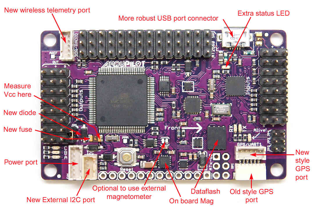
The board used for motor control and sensor data acquisition is APM 2.5:
The motor is powered by the L298N driver. The driver can control up to two DC motors, in our case we will only use one, and it will allow us to control both the speed and direction of motor rotation.

| L298N Board | APM 2.6 (Ard. Mega) | Battery | Motor |
|---|---|---|---|
| ENA | 3-OUTPUT ( 8 ) | - | - |
| IN1 | 4-OUTPUT ( 7 ) | - | - |
| IN2 | 5-OUTPUT ( 6 ) | - | - |
| VMS | - | 12V | |
| GND | - | GND | |
| MOTOR A | - | - | M+ |
| MOTOR A | - | - | M- |
On one of the wheels I added a quadrature encoder for speed control. The encoder sensor is attached to the car's structure with a 3D part, and inside the wheel there is another part that acts as the encoder disk. 3D mode can be found here:
To download the stl files you can click on the following images


The encoder is calibrated for operation from 4.5 V to 5.5 V. The two outputs of the encoder are digital outputs that can be connected directly to digital input pins on most microcontrollers. Here, the two outputs are connected to digital inputs 2 and 3 (Arduino Mega), configured as external interrupts.
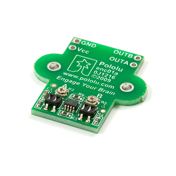
| Encoder Board | APM 2.6 (Ard. Mega) |
|---|---|
| OUTA | 6-OUTPUT ( 3 ) |
| OUTB | 7-OUTPUT ( 2 ) |
| Vcc | +5V |
| GND | GND |
The original servo has been replaced by a MG90S servo to control the vehicle direction. A 3D part has been printed to attach the new servo to the vehicle housing.

| Servo | APM 2.6 (Ard. Mega) |
|---|---|
| Signal | 2-OUTPUT ( 11 ) |
| Vcc | +5V |
| GND | GND |