![]()
![]()
This repository documents my research progress. I wanted to understand the necessary signal processing and control theory algorithms behind such a device.
The FFB pedal is a robot and can be dangerous. Please watch The Terminator before continuing. If not interacted with care, it may cause harm. I'm not responsible for any harm caused by this design suggestion. Use responsibly and at your own risk.
Shield:
This work is licensed under a Creative Commons Attribution-NonCommercial-ShareAlike 4.0 International License.

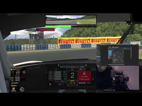
To tune the pedal parameters, a SimHub plugin was developed, which communicates with the pedal over USB.
Currently ABS, TC and RPM vibration are supported effects. The SimHub plugin communicates with the pedal and triggers game effects as parameterized.The effects and its description can be found in wiki.
The used microcontroller has software to communicate with the used iSV57 servo. Therefore, it can tune the servos PID loop and read certain servo states like position, torque, power.
The joystick/gamepad data is provided via three redundant channels
- Bluetooth
- 0V-3.3V output analog signal. Can be read by e.g. https://gp2040-ce.info/. The pin 25 was used for analog output.
- vJoy gamecontroller (only available when SimHub runs, also need enable control map plugin).
A lot of awesome devs have helped this project grow. Just to name a few:
- tjfenwick started the project with an initial implementation.
- tcfshcrw helped to elevate the Simhub plugin to its current form, added a ton of pedal effects, hardware and discord support, good guy and much more.
- MichaelJFr helped with refactoring the code at the beginning of this project. Fruitful discussions let to the implementation of the control-loop strategies.
- Ibakha Discord channel CEO.
Detailed descriptions of certain aspects can be found on the dedicated Wiki page:
A Discord server has been created to allow joint research.
The embedded code of this DIY FFB pedal runs on an ESP32 microcontroller. The PCB design was developed to prove the concept. It holds the ESP32, the ADC, a level shifter, and connectors. Currently, version 3 of this PCB design is used which introduced sensorless homing of the servo. The PCB design and pinout diagram can be found here. If you use Simucube wheelbase, you can use the D15 accessory port for input, detail was list here
Here is an image of the plain PCB:
![]()
Here is an image of the assembled PCB:

The PCB has three connectors with the following wiring:
| Connector at PCB | Servo |
|---|---|
| Dir- | Dir- |
| Dir+ | Dir+ |
| Pul- | Pul- |
| Pul+ | Pul+ |
| Connector at PCB | Servo |
|---|---|
| Gnd | Gnd |
| Tx | Rx |
| Rx | Tx |
| Connector at PCB | Loadcell |
|---|---|
| 5V | V+ |
| Gnd | V- |
| Gnd | Shield |
| S+ | S+ |
| S- | S- |
It is recommended to use a Schottky diode in the positive line from the PSU to the servo. The plated side faces the servo.
| PSU | Servo |
|---|---|
| 36V/48V | Vdd+ |
| Gnd | Gnd |
Depending on the load direction, the servo will act as a generator. It will produce an additional current flow from the servo to the PSU which could trigger the over-voltage protection from the PSU and the servo. To prevent the reverse current flow to the PSU and thus prevent over-voltage protection from the PSU, a Schottky diode was added to the power line. To prevent the trigger of the over-voltage protection from the servo a large capacitor was added in the power-line.
| Component | Link |
|---|---|
| SR5100 Schottky diode | Amazon.de |
| 100V 10kF capacitor | Amazon.de |
To hold the components, a power PCB was developed, which also featured a port to hold XT30 connectors. The
Here is an image of the plain PCB:

Here is an image of the assembled PCB:

A graph of the voltage fluctuations introduced by generative current flow from the servo can be seen here:

Without the capacitor these fluctuations would be much higher eventually triggering the servos overvoltage protection.
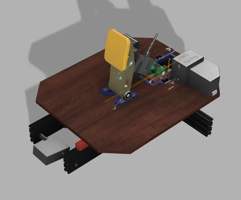
Here are some examples of mechanical designs awesome DIYers have done:
| Design | Link |
|---|---|
 |
Tjfenwick's design |
 |
Bjoes design |
 |
GWiz's design |
 |
shf90's design |
The BOM refers to the pedal design which I have chosen, see here.
A Doxygen report of the sources can be found here.
The drivers can be found here here.
Firmware can be built and flashed via Arduino-IDE or Arduino-CLI.
- Install the ESP32 dependencies in Arduino-IDE, see e.g. here
- Install the libraries
- Flash the code, e.g. via Ardiuno-IDE to esp32.
- Install the Arduino CLI
- Install the libraries
git submodule update --init --recursive - Execute the build script from a local repo.
- Flash the binaries via e.g. web installer, see below.
The binaries are available here. They can be flashed via the ESP webflasher.
| Memory address | File |
|---|---|
| 0x1000 | Main.ino.bootloader.bin |
| 0x8000 | Main.ino.partitions.bin |
| 0xe000 | boot_app0.bin |
| 0x10000 | Main.ino.bin |
The iSV57T allows parameter tuning via its RS232 interface. To tune the servo towards this application, I executed the following steps.
With the current PCB design, the ESP can directly communicate with the iSV57T servo. Manual tuning as described before isn't necessary anymore. A description of the steps I undertook to decode the communication protocol can be found on the Disord server. Additional features such as sensorless homing and lost-step recovery were developed and integrated with the help of this communication.
The SimHub plugin was designed to communicate with the ESP to (a) modify the pedal configuration, e.g. the force vs. travel parameterization and (b) to trigger effects such as ABS oscillations.

To install the plugin, the plugin DiyActivePedal.dll has to be copied to the SimHub directory, e.g. C:/Program Files (x86)/SimHub
The pedal will not move initially after flashing. One has to open the SimHub plugin, connect to the pedal, and send a config with non-zero PID values. Recommended PID values are:
P=0.2-0.4
I=50-150
D=0
After sending the initial config, power cycling of the pedal is necessary. The pedal should move afterward.
- Make sure, that you follow the above instructions. The default PID values are set to 0 thus the pedal will not move. You have to send non-zero PID values and restart the pedal to observe pedal travel.
- Open the serial monitor in Arduino IDE, set the baud rate to 921600, and restart the pedal. You should see some debug info. Make a screenshot and kindly ask the Discord server for help.
Install DirectX 9
Install a SimHub plugin matching the ESP firmware you installed and send a config to the pedal.
Check the arduino plugin scan setting, please use scan only specfiec port as below.

To get a better understanding of the motion and forces, a python script for simulation of the pedal angle, the pedal angular velocity and maximum pedal force has been written. Feel free to tune the pedal geometry as needed. The simulation result for my pedal geometry looks as follows:

ESP code:
- Add automatic system identification of pedal response
- Add model-predictive-control to the ESP code for the improved pedal response
- Add field to invert motor and losdcell direction
- send joystick data to simhub plugin and provide data as vJoy gamecontroller
- allow effects to move stepper beyond configured max/min position, but not the measured homing positions
- Optimize iSV57 communication
- Let the communication task run from the beginning of the setup routine
- Read pedal state every cycle (currently, the pedal performance is degraded)
SimHub plugin:
- Send SimHub data via wifi to ESP
- GUI design improvements for the SimHub plugin
- JSON deserialization make compatible with older revisions
- include the types header file and use it
- Make use of effects from the ShakeIt plugin
- add OTA update for esp firmware
- automatic serial monitor update
- serial plotter
- add different abs effect patterns, e.g. sawtooth
- make effects proportional to force or travel selectable by dropdown menu
Misc:
- Create a video describing the build progress and the features
- Add Doxygen + Graphviz to the project to automatically generate documentation, architectural design overview, etc.