Geometry Type: Multiple
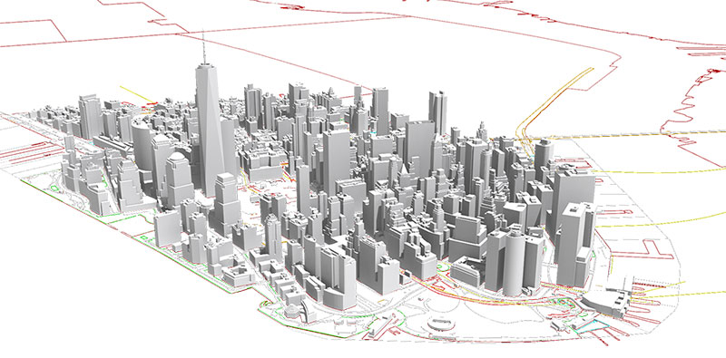
Table of Contents
1. Identification
2. Data Quality and Specifications
3. Attribute Information
| Purpose | 3-D Building Models were developed to supplement the most recent planimetric update. Some examples of usage include wind or shadow simulations, urban design, and building volume determination. Examples of NYC 3-D Building Model usage include: CESIUM (Open Source 3D rendering library) NY Times Shadow Study |
| Description | 3-D Building Models representing every NYC building present in the 2014 aerial survey. Models are based on a hybrid of the CItyGML Level of Detail (LOD) 1 (simple/prismatic buildings with flat roof detail) and LOD 2 (includes roof structure details) with approximately 100 iconic buildings modeled to LOD 2. Highlights of the model include the differentiation of building components including roof, facades, and ground plane. |
| Source(s) | Department of Information Technology & Telecommunications (DOITT) |
| Publication Dates | Data: 04/18/2016 Last Update: 04/18/2016 Metadata: 12/28/2016 Update Frequency: The 3-D model was a one-time capture. Updates and extensions may be considered in the future. |
| Available Formats | 3-D Model data is available in the following formats: CityGML : 894 MB Multipatch (ESRI) : 251 MB DGN (Microstation) : 744 MB |
| Use Limitations | Open Data policies and restrictions apply. See Terms of Use |
| Access Rights | Public |
| Links | https://data.cityofnewyork.us/City-Government/3-D-Building-Model/tnru-abg2 |
| Tags | doitt, gis, 3d, buildings, model |
| Horizontal Coordinate System | New York State Plane Coordinates, Long Island East Zone, NAD83, US foot |
| Resolution | ASPRS CLASS 1.5 for 1"=100' scale maps |
| Spatial Coverage | New York City, NY |
| Temporal Coverage | Data is based on buildings present in 2014 aerial survey. |
| Positional Accuracy | 3-D models are based on the planimetrics building footprint feature class. The horizontal accuracy (XY) of all planimetric feature classes captured is such that 95% of features are within (plus/minus) 1.25 ft of the actual horizontal location. The vertical accuracy (Z) of all planimetric feature classes with elevation values is such that 95% of features captured are within (plus/minus) 1.6 ft of the actual elevation. |
| Features Captured | Permanent structures (e.g. stairwells, towers, etc) with lengths greater than 10' on a side or minimum 100 sq. ft. were captured. Features that are less than 10' but also align with the building planimetric outline are also included. |
| Features Excluded | For LOD 1.5 buildings, domes and pitched roofs are not rendered. All roof appendages, such as chimneys, parapets, spindles, and antenna are also not included. For buildings with complex or multiple roof structures, a generalized collection method was used. Small permanent structures (e.g. small towers, elevator shaft, stairs) with less than 10' on a side were not captured. |
| Capture and Update Notes | 3-D building models were created by stereo compilation with BAE Systems' SocetSET GXP/Hexagon SSK software. Models are based on 2014 aerial photos and the building footprints feature class from the planimetric database. Using the Open Geospatial Consortium's CityGML standards as the basis, the model was developed to a hybrid specification combining elements from Level of Detail (LOD) 1 and 2. When possible, the elevation attributes (ground elevation and roof height) from the building footprint feature class were used for building base and top data collection to ensure vertical consistency. Since roof elevations from the building feature class are based on the highest point of the roof, there are some differences in elevation for the 3D roof infrastructure that is modeled. Once building roof polygons were created, a digital elevation model (DEM) was used as a ground lattice in conjunction with building base elevation to create a solid model of the buildings. The model was then populated with projection parameters. For LOD 1.5 features, multiple roofs less than 8ft difference were considered as one roof outline and elevation points were placed at the highest point within the roof. For LOD 2 all ridges, dbomes and partitions were captured and assigned elevations with microstation tools. Approximately 100 iconic buildings were created in LOD 2. Building data was then converted from DGN/ESRI multipatch file geodatabase formats to CityGML using Safe Software's Feature Manipulation Engine (FME). Examples of LOD 1.5 and LOD 2 buildings can be seen in the images below.   The model was a one-time capture. If the model is useful, future updates and extensions will be considered. |
| Attribute | Description | Field Type | Sensitive Field (Y/N) | Notes |
|---|---|---|---|---|
| BIN | Building identification number. Assigned by City Planning | numeric | No | |
| DOITT_ID | Unique identifier assigned by DOITT. | numeric | No | |
| SOURCE_ID | numeric | No |