[Problem] TechDraw Dimensions are corrupted on recompute #8878
Comments
|
There are two aspects of the problem:
In order to solve the first aspect, we need to know that the geometry being referenced by the dimension is not the geometry that was originally referenced. This requires saving a copy of the referenced geometry for comparison. Geometry is a relatively lightweight object, so saving a copy of an edge or a few vertices is not a problem. Comparing geometry is a difficult undertaking - there is no "==" operator for geometry. In a complete solution, we would need to consider changes in scale or positioning as well as actual changes in the geometry, such as a line becoming longer or a radius getting bigger. The problem has some similarities with feature detection in computer vision applications. The general flow of the comparison process is: The extraction of characteristics controls how "good" our comparison will be. A simple comparison of line endpoints or circle centre and radius should be sufficient to detect cases where the geometry has not changed, but has been renamed. A more detailed set of characteristics would be required to detect the situation where the geometry has moved. Once we have detected a mismatch, we need to take action. This may be just a message to the user, or an automatic replacement of the erroneous reference with a correct one. To automatically replace the erroneous reference, we need to search through the candidate geometries, extract the characteristics, compare to our saved geometry's characteristics and use the best match to update the reference. Determining the best match can be as simple as selecting the first matching geometry or as complex as scoring each candidate and comparing the scores. The general flow of the replacement process is: |
|
Implementation details DrawViewDimension DimensionReference new GeometryMatcher QGIViewDimension |
|
Sounds wonderful to me! I've also thought about implementing a similar mechanism in the past, but I've failed to come up with a decent edge/vertex comparison algorithm for the feature even in the abstract idea level when the model is edited (i.e. the stuff where you refer to computer vision algorithm). Thus, the lack of a good algorithm and the expected difficulties with an even very basic implementation has kept me at bay for this kind of functionality; but it's great to hear that you've already managed to design and implement some parts of the functionality. In practice, I'm suspecting that the main problem will be the "superfluous geometry" that the OCC algorithms sometimes produces. Every now and then, OCC produces multiple edges that are partly or fully overlapping, and sometimes these extra edges are thrown out by OCC. If two edges happen to have exactly the same geometry, it's obviously impossible to detect which one is which. Thus, there would need to be a mechanism to get rid of fully overlapping edges before any other processing is done to the drawing, but I'm afraid this kind of function is missing from TD (or OCC). |
|
If two edges are identical, does it matter which one we pick? We do remove overlapping edges in the new FaceFinder algos (DrawProjectSplit::removeOverlapEdges). It is a bit time consuming, but maybe we should just scrub the edge pile at the beginning. |
Well, you're right that with absolutely identical edges it probably shouldn't matter because they can be re-swapped during dimension fixing if they happen to swap in OCC, but quite often the superfluous edges seem to be shorter parts of the "real" edges that fully overlap other edges. The short and long arc parts of the same "real" arc are not freely swappable, and the short parts may disappear after OCC update, which may turn up to be a problem if the user has (accidentally) attached a dimension to a such short edge. This happens especially with arcs and other round shapes when there are e.g. concentric circles in the 3D model that are flattened on top of each other in the projection.
Sounds like a good idea to me, if these new algorithms are really able to strip out these short overlapping edges. I wasn't aware of that addition. I think the extra edge pieces are a nuisance even without any dimension corruption problems taken into account, because sometimes one accidentally selects one of those split edge pieces instead of the proper long edge in the GUI. |
|
Scrubbing the edge pile to remove overlaps costs between 0.5 and 1 sec in my quick tests. We might be able to get some of that back by not having to scrub when making the faces.
|
|
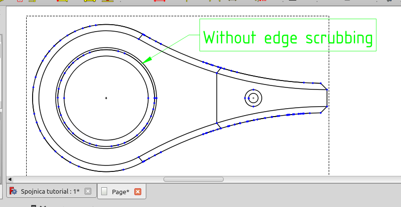
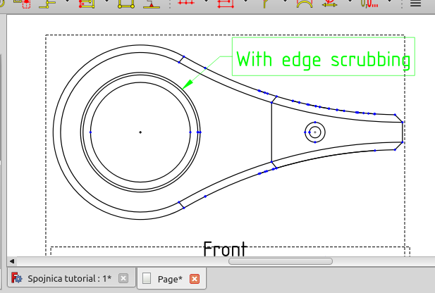
from user testing (https://forum.freecad.org/viewtopic.php?p=668208#p668208) of proof of concept: |
Sounds very promising, and I suggest that edge scrubbing should be always done first! I mean, if it uses some seconds of computer time instead of many minutes or hours of manual editing time for the user it's definitely worth it. However, if the screenshots are accurate there is potential for improvement in the edge scrubbing algorithm: It has somehow increased the number of blue dots in the top right part of the drawing compared to the unscrubbed case. Could it be that the algorithm has scrubbed the long edge away, and kept the chain of the smaller edges instead? Perhaps it might be feasible to develop an improvement to the algorithm that tries to scrub the edges in length order (shortest first)? |
|
"It has somehow increased the number of blue dots in the top right part of the drawing compared to the unscrubbed case. " That might be partial overlaps being split into non-overlapping segments. Will have to do some debugging to be sure. |
|
PR for phase 1 submitted - #8989 |
|
one possible approach to phase 2: |
|
Another approach. More difficult to implement, but maybe better long term? |

|
Wouldn't the neural network edge matching be essentially the same as the scoring algorithm, unless you'd have much more extraneous neurons that you'd train with some test data. The difficulty would be obtaining good-enough large set of hand-fixed cases, and probably the slowness of the algorithm if there are enough neurons. Thus, I'd suggest to at least first implement the simpler scoring algorithm. In general I guess the scoring algorithm should give highest scores for exact matches, high scores for edge type matches, and medium linearly adjustable scores for scaled for position differences, length differences, angular differences for straight edges, radius differences, etc, so that the score is highest when difference is zero, and probably go by difference squared type of scaling to reduce the score. Spline scoring I have no idea about. For solving the problem with the scoring algorithm, there are the difficult cases of scale change and the ISO count. The scale change should probably be detected independently (there are two sub-cases, changing the TD scale and scaling the 3D model itself). The ISO count case is more difficult, because an edge dimension might be split into a dimension with the end points at two different edges (you'd have to actually track the vertices to solve this). |
|
Yeah, the procedural scoring approach will probably come first. The reason I was thinking about neural networks is that I don't know how people can so easily detect that newedge == oldedge and we could maybe teach the network with a bunch of solved cases (and maybe use GPU for large models). We only have to deal with splines that are representing circles, so we can use spline.asCircle to reduce the problem to the circle case. Scale shouldn't be a problem for 2d, as we already unscale the saved geometry, then unscale the candidates at comparison time. I don't have any ideas about the iso lines breaking up edges at the moment. |
How so? I thought the user would be able to attach (distance) dimensions to various different spline edges, and they should be handled somehow, too?
Well, that's good!
Yes. Any implementation should likely be endpoint-based, which means that the algorithm should find a Dimension endpoint vertices, and determine which two (three) used to be attached to the Dimension, and then find out in which edges those are after the change. Quite complicated and error-prone... That needs to be thought out more sometime later, I guess. Luckily ISO count adjustments are rarely done in practice. |
|
"How so? I thought the user would be able to attach (distance) dimensions to various different spline edges, and they should be handled somehow, too?" Hmmm, you're right. We do have point to edge and edge to edge distance dimensions, and those edges can be splines. Maybe we'll get lines and circles working, and then figure out how to compare splines. |
You'd probably get away by comparing the spline start and endpoint locations; and later on add edge pythagorean length (distance between spline endpoints) + the vector angle between startpoint and endpoint. It's an heuristic, it doesn't have to be accurate, and for most cases these values differ at least a little for splines, anyways. And it'll be straightforward to add a better algorithm later on. I'd definitely agree to make the circular arc comparisons for those splines that can be directly converted to circular arcs, though. |
|
Phase two of error correction will attempt to pick a new reference for Line and Circle edge references and Vertex references. All tests results are mapped onto [-1, +1], with -1 indicating not a good match and +1 indicating a very good match. Closeness tests use a "tolerance" of 10% of model size as a preliminary check. A point more than tolerance away from reference scores -1. Closeness on [0, tolerance] is mapped to [-1, +1]. Scalar tests use an absolute tolerance of 5 as the preliminary check. Angular tests (directions) use a tolerance of M_PI / 10.0 as the preliminary check. Bounding Box test is binary: +1 if boxes overlap, -1 if they don't. |
|
Phase two includes the following checks: Implemented tests and weights for line edges: Implemented tests and weights for circle edges Implemented tests and weights for vertices |
|
Still need to develop a scheme for adjusting the weights of the various tests. |
Is there an existing issue for this?
Version
0.21 (Development)
Full version info
Subproject(s) affected?
Techdraw
Problem description
TechDraw dimensions use the traditional geometry + index name ("EDGE5") to identify model elements. These names can change when the base model changes (the "Topological Naming Problem") and also when the OCC Hidden Line Removal algorithm is executed.
When these names change (more precisely, when "EDGE5" now refers to a different edge), the dimension may become corrupt, or worse, report an incorrect value without warning.
A typical user reaction to this problem: https://forum.freecad.org/viewtopic.php?t=75364
This problem can be mitigated to some extent by using references to the 3d model instead of to lines on the drawing. This is easier than it once was, but is still not as convenient as selecting an edge in the drawing.
Ideally, each edge produced by the Hidden Line Removal algorithm would carry a persistent link to the original edge in the 3d model. This would require major changes to the OCC algorithm.
An alternative would be for the dimension to maintain a copy of the original geometry and report when the saved copy does not match the current state of the model. In this alternative, it would also be possible to "autocorrect" the dimension.
Anything else?
Forum discussion: https://forum.freecad.org/viewtopic.php?t=76815
Code of Conduct
The text was updated successfully, but these errors were encountered: