DIY RGB LED strip driver that can be connected to a smart home (HomeKit) using Raspberry Pi and Arduino.
This is a complete DIY guide going through all steps on how to build your own RGB LED Strip Driver that will be able to work together with Apple HomeKit. This will allow you to control the LED-strip wirelessly through the use of Siri. You simply tell Siri to turn on your LED-strip and set the color to e.g. red and through the combined work of the Raspberry Pi, Arduino Uno and a nicely crafted board, the strip will light up in the color of your choice.

"Hey Siri, put my LED Strip to red."
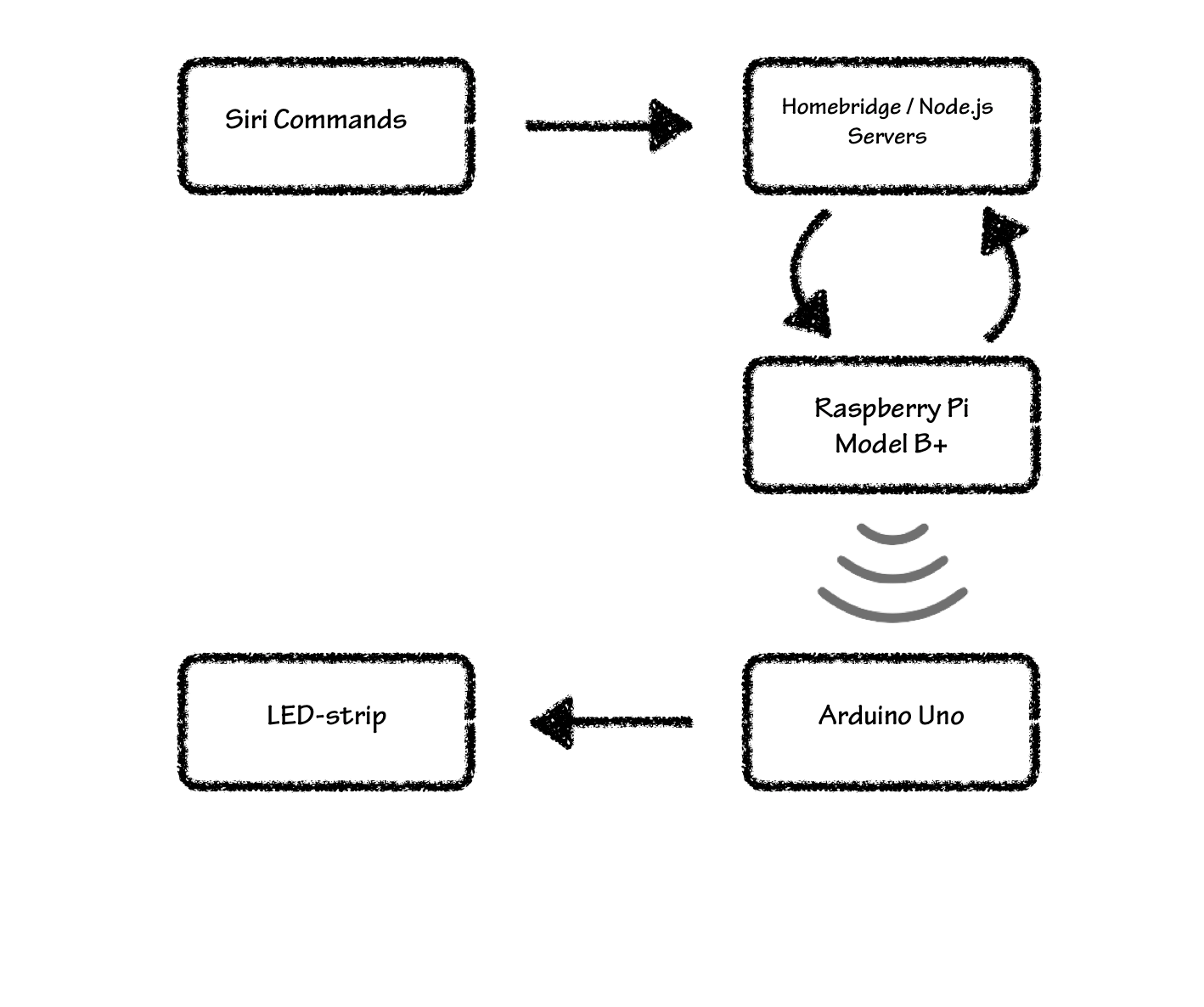
This illustrates briefly how the complete system works. Basically, by giving Siri or HomeKit on an Apple device a command, the command will be passed to a homebridge server running on the Raspberry Pi. This command will then be passed to a local node.js server that will execute a program which in-turn will send color data wirelessly to an Arduino that is controlling a LED strip.
- RGB-LED Strip (5m with 4 pins)
- Raspberry Pi 3 Model B+
- Arduino UNO
- 2x NRF24L01+ Radio transceiver
- 3x N-Channel MOSFET transistors (IRLB8721, BUZ100 or similar)
- 3x 160 Ohm Resistors
- Circuit Board or breadboard
You may use any type of N-Channel MOSFET as long as they can handle the amount of current that your LED-strip requires per color channel.
Depending on your resources you can create your PCB as you want as long you follow the following schematic: (rgb-board.sch)
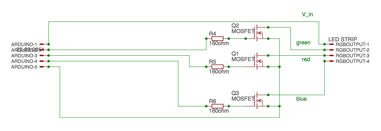
We will provide an EAGLE file so that it can be milled on a double-sided copper plate using a PCB milling machine, but if you lack the resources, we will also include illustrative pictures of how to do all of this using traditional breadboards.
If you are using a breadboard, this image can be helpful:

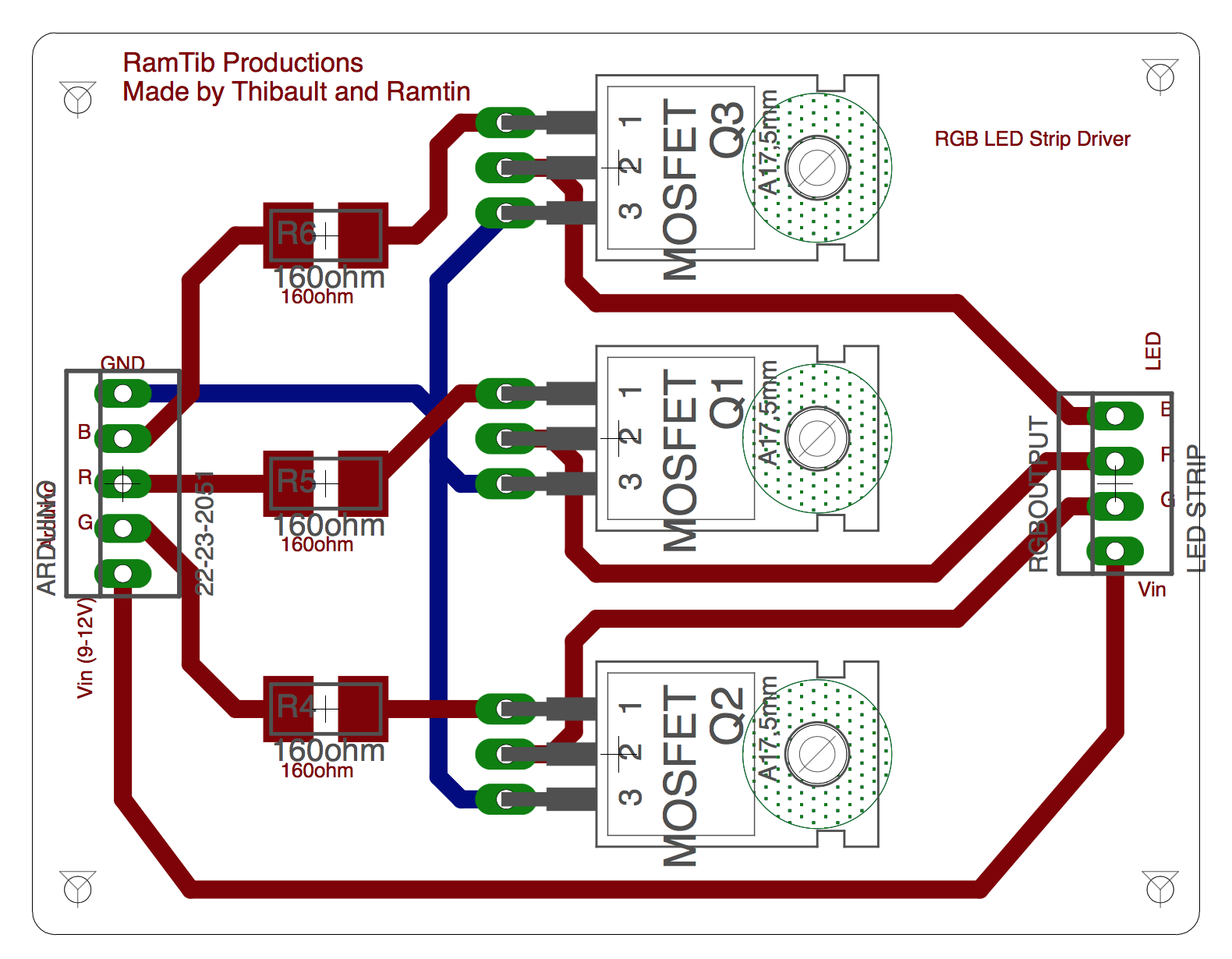
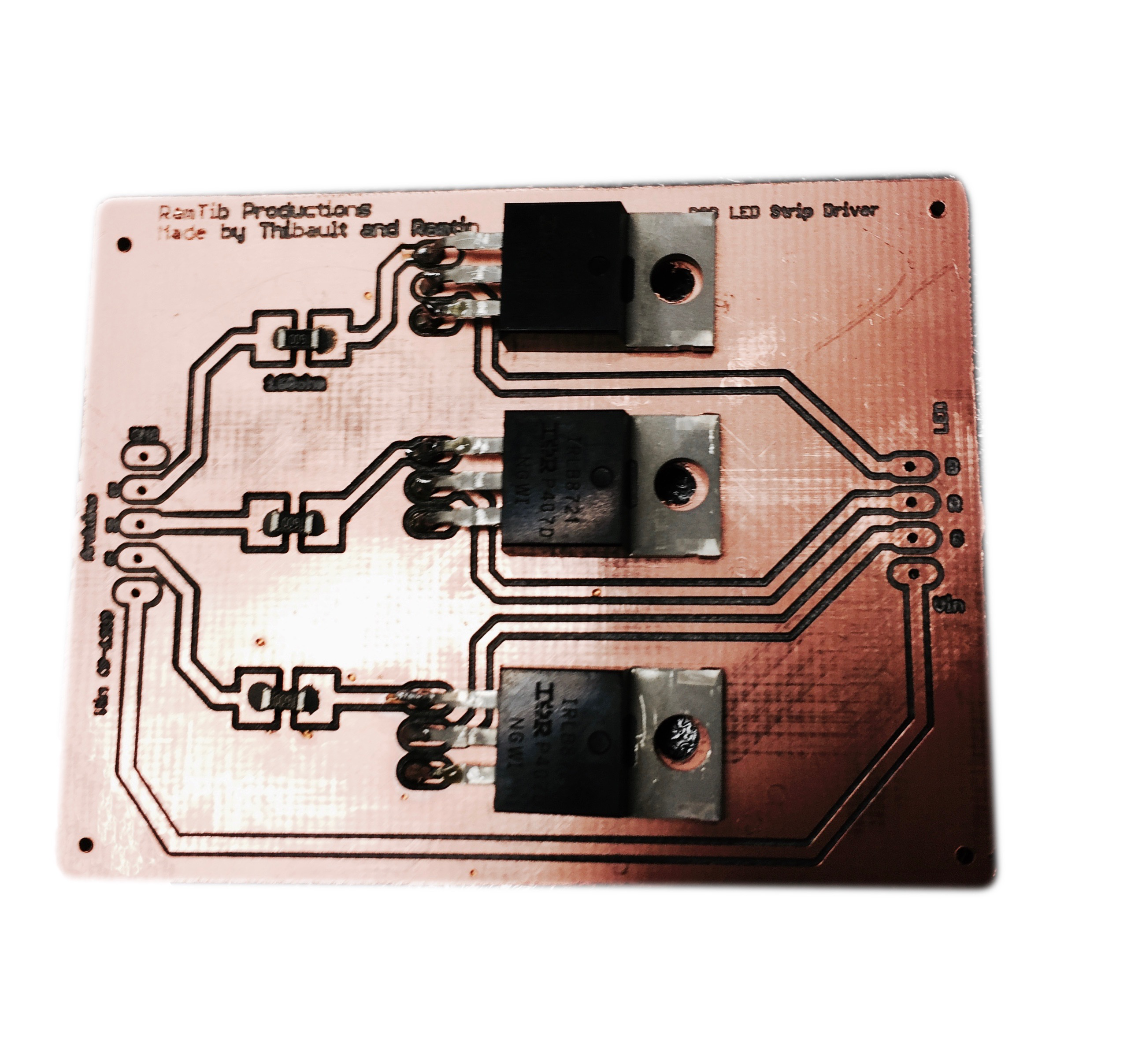
The left you see the EAGLE Board file design (rgb-board.brd) and to the right the result with the soldered transistors and resistors:
Now that the LED strip has been prepared with the Arduino, we will take a look at how to hook it up with the RF24-module to enable receiving signals from the Raspberry Pi.
This image shows how to connect the wireless transceiver to the Arduino pins.
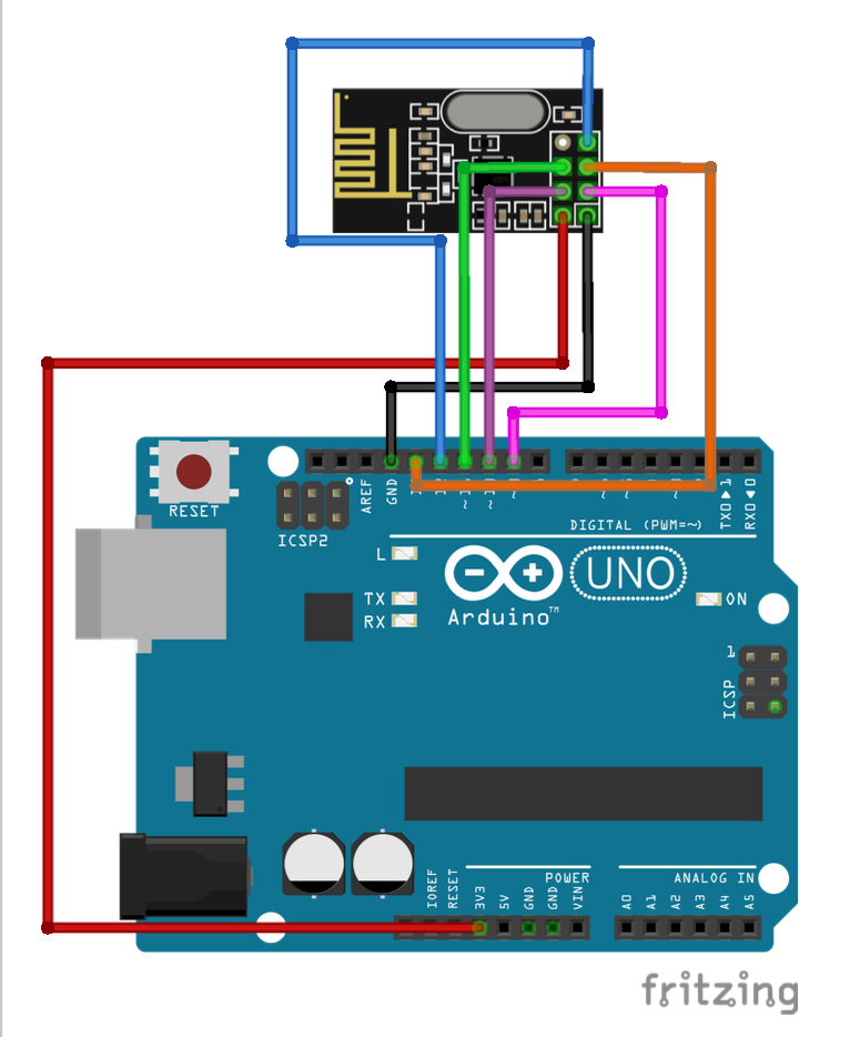
The following code is then implemented into the Arduino. (RGB_DRIVER.ino). Please note that the library RF24.h needs to be installed from e.g: https://github.com/maniacbug/RF24. The pins corresponds to the same pins as the pictures above and the same ID set to the parameterconst uint64_t pipe (i.e. in our case: 0xF0F0F0F0E1LL) will be used later on the Raspberry Pi program.
#include "nRF24L01.h"
#include "RF24.h"
#include "RF24_config.h"
#include <SPI.h>
/////////////////////////////-RF24-////////////////////////////////////////
RF24 radio(9, 10); //RF24 pins
const uint64_t pipe = 0xF0F0F0F0E1LL; //ID
unsigned long RGB = 0;
/////////////////////////////////////////////////////////////////////////

//////////////////////////////-RGB-/////////////////////////////////////////
#define REDPIN 5
#define GREENPIN 6
#define BLUEPIN 3
#define FADESPEED 1     // make this higher to slow down fading
int r, g, b, rPrev, gPrev, bPrev, f = 0;
int blueMask = 0xFF0000, greenMask = 0xFF00, redMask = 0xFF; //decoding masks
//////////////////////////////////////////////////////////////////////////

void setup(void) {

  //Radio module setup
  radio.begin();
  radio.openReadingPipe(1, pipe);
  radio.startListening();

  //RGB setup
  pinMode(REDPIN, OUTPUT);
  pinMode(GREENPIN, OUTPUT);
  pinMode(BLUEPIN, OUTPUT);

  //serial Setup
  Serial.begin(9600);
  Serial.println("Started Listening...");
}

void loop(void)
{

  if (radio.available()) { //signal received

    if ( !radio.read(&RGB, sizeof(unsigned long)) ) {
      Serial.println("ACK not received by client.");
    }

    //save previous values
    rPrev = r;
    gPrev = g;
    bPrev = b;
    int[3] prevColors = [rPrev, gPrev, bPrev]; //array with previous color values

    //decode RGB values
    r = (RGB & 0xFF);
    g = ((RGB & 0xFF00) >> 8);
    b = ((RGB & 0xFF0000) >> 16);
    int[3] colors = [r,g,b]; //array with color values

    Serial.print("Received RGB-value: R= "); Serial.print(r); Serial.print(", G= ");
    Serial.print(g); Serial.print(", B= "); Serial.println(b);

    //change color with a smooth transition
    changeColor(colors, prevColors);

  }
}

//change color with a smooth transition
void changeColor(int[3] colors, int[3]prevColors){
  //To determine increase or decrease
  int diffR = colors[0]-prevColors[0];
  int diffG = colors[1]-prevColors[1];
  int diffB = colors[2]-prevColors[2];

  int i = prevColors[0];
  int j = prevColors[1];
  int k = prevColors[2];

  while (i==r && j==g && k==b)
  {
    //Red color
    if (i!=r){
      if (diffR>0) i++;
      else  i--;
      analogWrite(REDPIN, i);

    }
    //Green color
    if (k!=g){
      if (diffG>0) j++;
      else  j--;
      analogWrite(GREENPIN, j);
    }
    //Blue color
    if (k!=b){
      if (diffB>0) k++;
      else  k--;
      analogWrite(BLUEPIN, k);
    }
    delay(FADESPEED);
  }
}
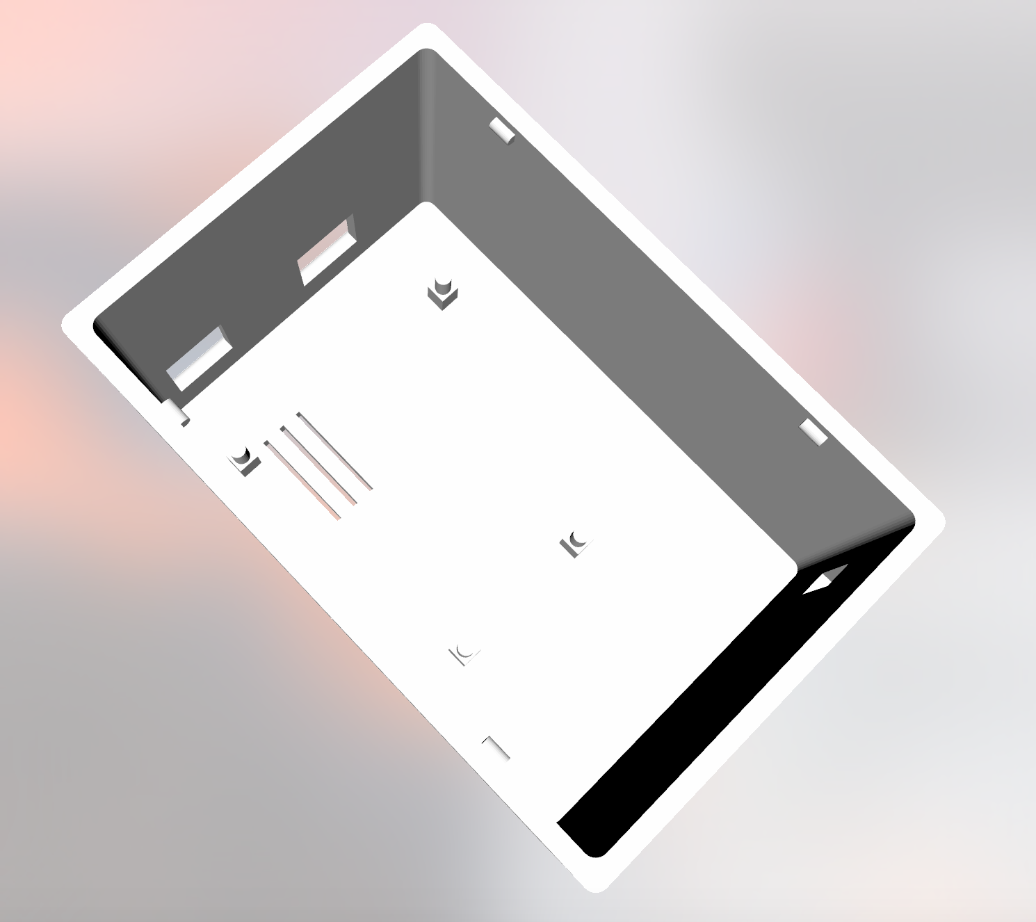
We provide you 3D CAD files for a 3D-printable box that fits an Arduino UNO and our PCB that we used. Depending on your circuit board dimensions you may need to create your own box. It needs 3 openings, one for the Arduino USB and DC inputs, and one RGB-LED strip output port (in our case 4 pins). The box should contain the Arduino, circuit board and RF24 transceiver with all its wires.

When the homebridge and node.js servers are running on the Raspberry Pi they will need to send the data received from HomeKit to the Arduino wirelessly. The image below shows how to connect the RF24 transceiver to Raspberry Pi using GPIO pins.
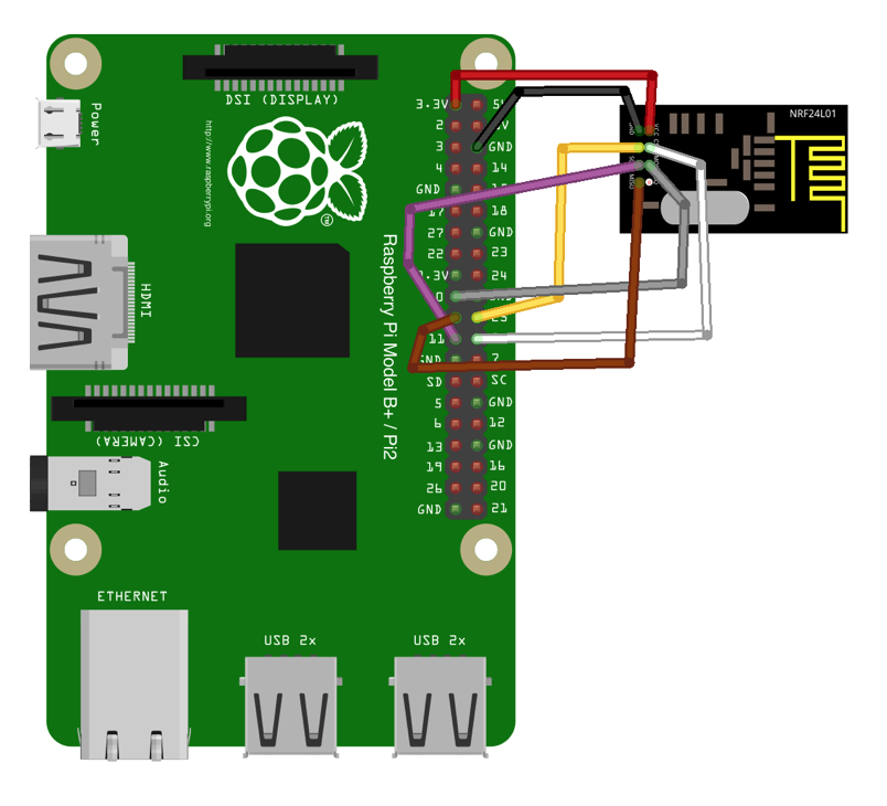
This C++ program (RF24-remote.cpp + makefile) will be executed by the node.js server and send data through the transceiver. Please note that the library RF24.h must be installed from github (link:TMRh20) for it to compile and install successfully.
#include <cstdlib>
#include <math.h>
#include <iostream>
#include <sstream>
#include <string>
#include <unistd.h>
#include <RF24/RF24.h>

using namespace std;

//RPi genericpinconnection                                                      $
RF24 radio(25,8);

// Radio pipe addresses for the 2 nodes to communicate.
const uint64_t pipes[2] = { 0xF0F0F0F0E1LL, 0xF0F0F0F0D2LL };

int main(int argc, char** argv){
        unsigned int RGB=atoi(argv[1]);
        cout << "Sending message to LED-Driver…\n";
if (argv[1]){
                // Setup and configure rf radio
                radio.begin();

                // Dump the configuration of the rf unit for debugging
                //radio.printDetails();

        radio.openWritingPipe(pipes[0]);

                printf("Now sending (RGB: %d)...\n", RGB);
bool ok = radio.write( &RGB, sizeof(unsigned int) ); //send mes$

if (!ok){
                        printf("Failed.\n");
                        return 0;
                }else printf("Message Sent!\n");

        }else printf("Message not sent. No argument was given…\n");
  return 0;
}Now that all hardware is connected and its corresponding code implemented, the last and a bit tricky part of this guide is left.
First you will need to install homebridge on your Raspberry Pi by following this guide: link: https://github.com/nfarina/homebridge/wiki/Running-HomeBridge-on-a-Raspberry-Pi.
After you have managed to successfully install homebridge you will need to create a background service for it using serviced. Look at this guide: https://github.com/nfarina/homebridge/wiki/Running-HomeBridge-on-a-Raspberry-Pi#running-homebridge-on-bootup-systemd.
By doing that it will automatically start on boot and as well after eventual crashes.
You will have to install this plugin: npm -install http-better-rgb.
Then you can use this config.js sample code for homebridge:
{
        "bridge": {
                "name": "Homebridge",
                "pin": "987-65-431",
                "username": "CC:22:3D:E3:CE:32"
        },

"accessory": "HTTP-RGB",
        "name": "LED Strip",

        "switch": {
            "status": "http://localhost:8080/",
            "powerOn": "http://localhost:8080/",
            "powerOff": "http://localhost:8080/?name=0"
        },

        "brightness": {
            "status": "http://localhost:8080/",
            "url": "http://localhost:8080/?name=%s"
        },

        "color": {
            "status": "http://localhost:8080/",
            "url": "http://localhost:8080/?name=%s",
            "brightness": false
        }
}
]
}
You can also add other accessories that you already have in your home that are compatible with various homebridge plugins.
Using apache2 and nodejs we can run this server on localhost. This plugins need to be installed for it to work: npm -install -g hex-rgband npm -install -g http.
#!/usr/bin/env nodejs
var http = require('http');
var url = require('url');
var hexRgb = require('hex-rgb');
const exe = require('child_process').exec;

var hex;
var rgb

var server = http.createServer(function(req, res) {

  var queryData = url.parse(req.url, true).query;
  res.writeHead(200);

  if (queryData.name) {
    hex=queryData.name;
    var rgb_temp=hexRgb(hex); //convert to rgb from hex

    //encode to 24-bit RGB value

    //command to run
    var cmd = 'sudo rf24-RGB-remote ' +rgb;

    exe( cmd ,(error, stdout, stderr) => {
      if (error) {
        throw error;
      }
      //console output
      console.log('--------\nHEX-value: '+hex+", RGB-value: "+rgb_temp+"\n");

      //output on web page
      res.end('RGB-remote server is running! \nRGB-value=' + rgb+'\n\nRF24:');
    });

  }     else { //no argument
    res.end("Server is running! No hex value was given in url... ");
  }

});
server.listen(8080);

console.log('Starting server. Listening on localhost:8080');