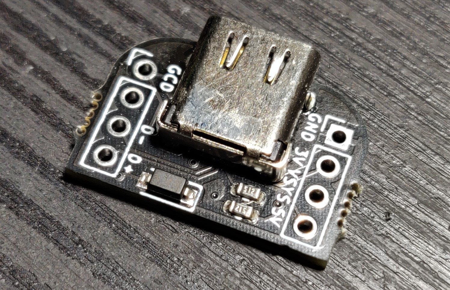
The Model UD is a USB C breakout board based on the Model U designed by Crane. It is exactly the same size and footprint as the Model U but integrates a schottky diode directly onto the board and adds the "VSYS" pin. This eliminates the need to add a stand alone diode to your circuit when wiring to a Raspberry Pi Pico. You can simply run a wire directly from the VSYS pin on the model UD to the VSYS pin on the Pico.
The Model UD is specifically designed for use with DIY rectangle controllers to facilitate the use of USB C to GC cables as well as standard USB C to USB A cables.
I sell these on my Etsy shop.
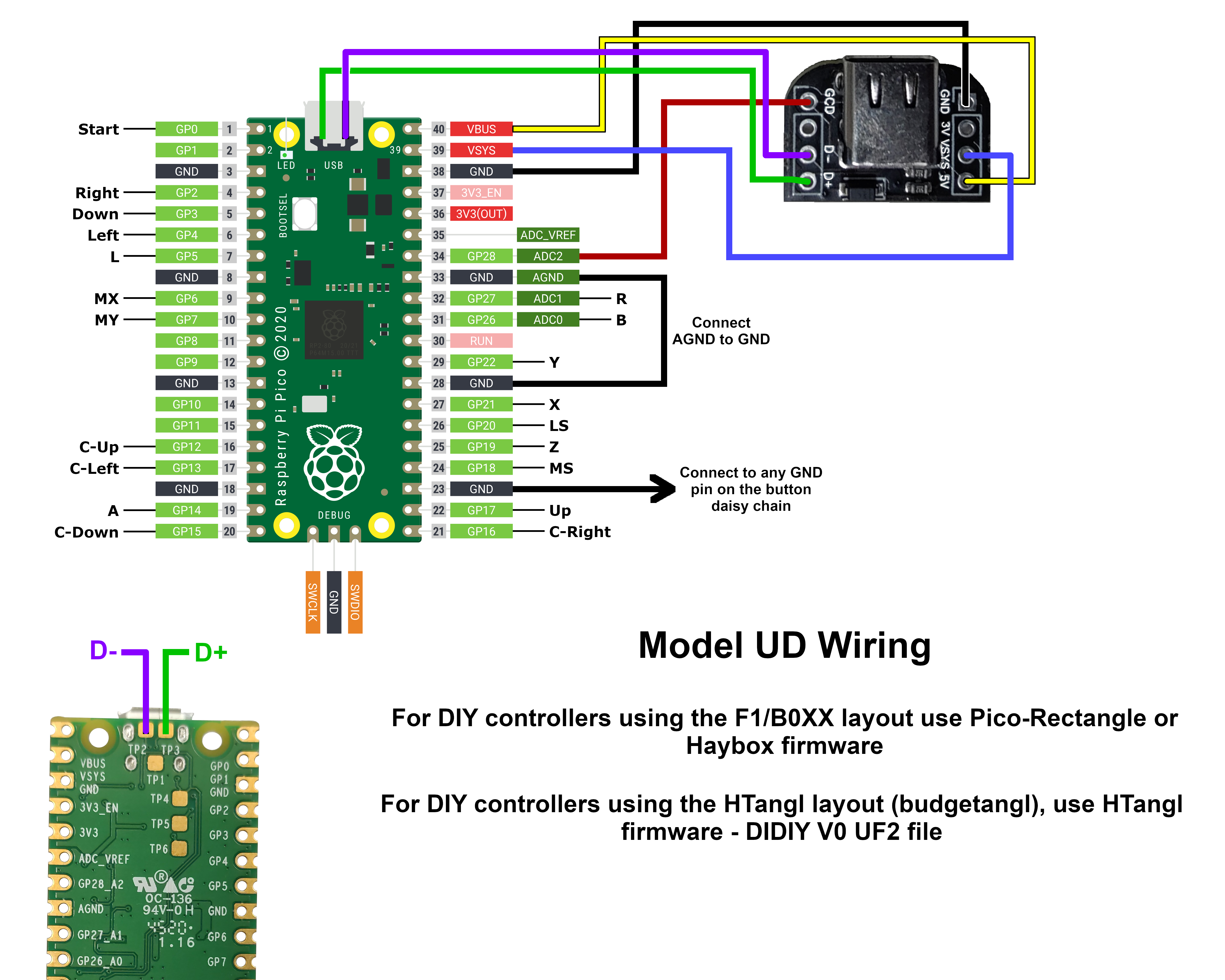
Here is a wiring guide.
This repository contains the files necessary to order these boards from JLCPCB.
Please be aware that JLC does not have a great track record when it comes to SMT part assembly.
It is normal to receive 1 to 4 bad boards in every batch.
There is a guide at the bottom of this page that explains how to test the boards.
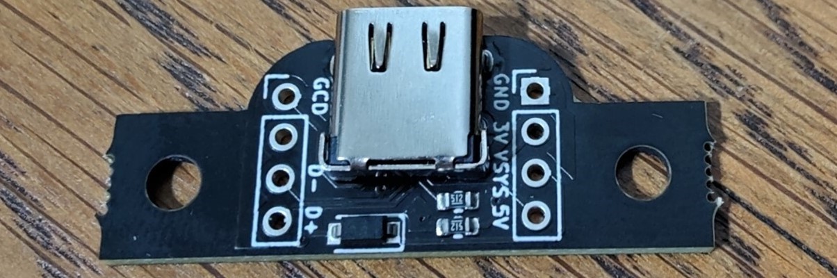
There are also files for a modified version of the board with 3mm mounting holes added if you plan to mount the board with screws. These are the "Model BirdD" files, cuz they kinda look like a Model UD with wings.
-
Download the files from this repository by clicking on "Code" and then on "Download Zip". Unzip the "Model-UD-main.zip" but do not unzip the "Model-UD_panel.zip" folders

-
From the JLCPCB home page click on "Order now"

-
On the next page click the "Add gerber file" button and select one of the "Model-UD_panel.zip" files in the "Model-UD JLC Files" folder. For this guide I'm using the 10 piece panel. Keep in mind JLC's minimum order quantity is 5 so since I'm using the 10 piece panel file I will end up with 50 individual breakout boards total.

-
Change the delivery format to "Panel by Customer" and then input the amount of rows and columns needed, for the 10 piece panel it is 2 columns and 5 rows

-
Scroll down and turn on the "SMT Assembly" slider, leave everything default and then click "Confirm"

-
On the next page add the BOM and CPL files from the "Model-UD JLC Files" folder. Then select the "Single Piece" button and then click "NEXT"

-
On this page just leave everything default and click "NEXT"

-
The final step will show you a preview of what the boards will look like. It is normal for the parts to be off center and only displayed on one board. JLC will place the parts correctly after you place the order. Also note that if you are ordering less than 50 individual breakout boards you will still be charged for 100 resistors, this is normal and is just a JLC policy. For some small parts they have a minimum quantity. Lastly please do not use the price listed in this picture as a reference, the price shown doesn't include tax or shipping and JLC does change their price from time to time. All you have to do now is click "SAVE TO CART" and then finish the checkout process


If you plan to sell these I recommend testing them first.
To do this you will need a USB C to USB C 3.1 gen 2 cable and a 24 pin USB C breakout board.
Here are links to the breakout board and cable that I use.
Breakout: https://amazon.com/dp/B07771CFFM or https://amazon.com/dp/B09L816S5W
USB Cable: https://amazon.com/dp/B07THFJ1J5
To test the boards you need a multi-meter with a continuity testing mode.
Start by connecting the Model UD to the 24 pin breakout.
Next put one lead of the meter on any pin of the Model UD and then drag the other lead of your meter across every pin on the 24 pin breakout.
Use the chart below to determine which pins should have continuity.
If you get continuity on a pin that should not have continuity, such as D+ on the Model UD getting continuity on a GND pin, then the Model UD is broken.
The pins on the left are the Model UD and the right is the 24 pin breakout.
Please note that if you'd like to test the diode connected to the VSYS pin you will need a meter with a diode test mode and test between the VSYS and 3V pins, this is generally not needed as the chance of having a bad diode is extremely low.
5V - VBUS (A4, A9, B4, B9)
3V - RX1/2+ (A11, B11)
Gnd - GND and Shield (if applicable) (A1, A12, B1, B12)
D+ - D+ (Either A6 or B6 you will only get continuity on one)
D3V - TX1/2+ (A2, B2)