flashing and wiring CC2530 #88
Comments
|
Maybe @ptvoinfo or @kirovilya can help with more information. |
|
@1981nick1982 For speedup you can buy dev-board like this https://www.aliexpress.com/item/ZigBee-CC2530-Sensor-Node-Baseboard-Functional-Module-Expansion-Board-USB-Port-24MHz-256KB/32767498002.html put CC2530 and connect CCDebugger to this board. After flashing, for using you need USB-TTL cable and connection: |
|
When you use the expansion board , is it still needed to use a USB-TTL cable. And which one do you recommend? |
|
@1981nick1982 With expansion board you not need USB-TTL. You will have to try to hide this board - this is the only problem :) Hide the cc2530 with a TTL cable without a board much easier. |
|
@kirovilya Hiding is not a problem. Next to the distribution box, I would place a cabinet in which I place the pi with the Zigbee2MQTT, Z-wave stick and an RFLink connected to it. The antennae of the RFLink and CC2530, I extend with a small piece of cable so that these come on the outside of the box. |
|
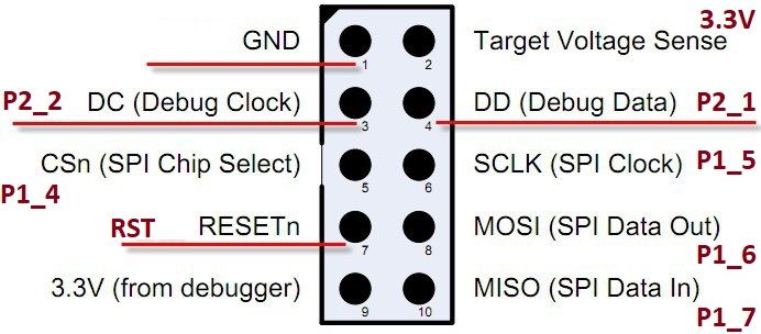
@1981nick1982 Uploading firmware: connect pins as showed http://ptvo.info/wp-content/uploads/2018/05/smartrf04eb-pinout.jpg |
|
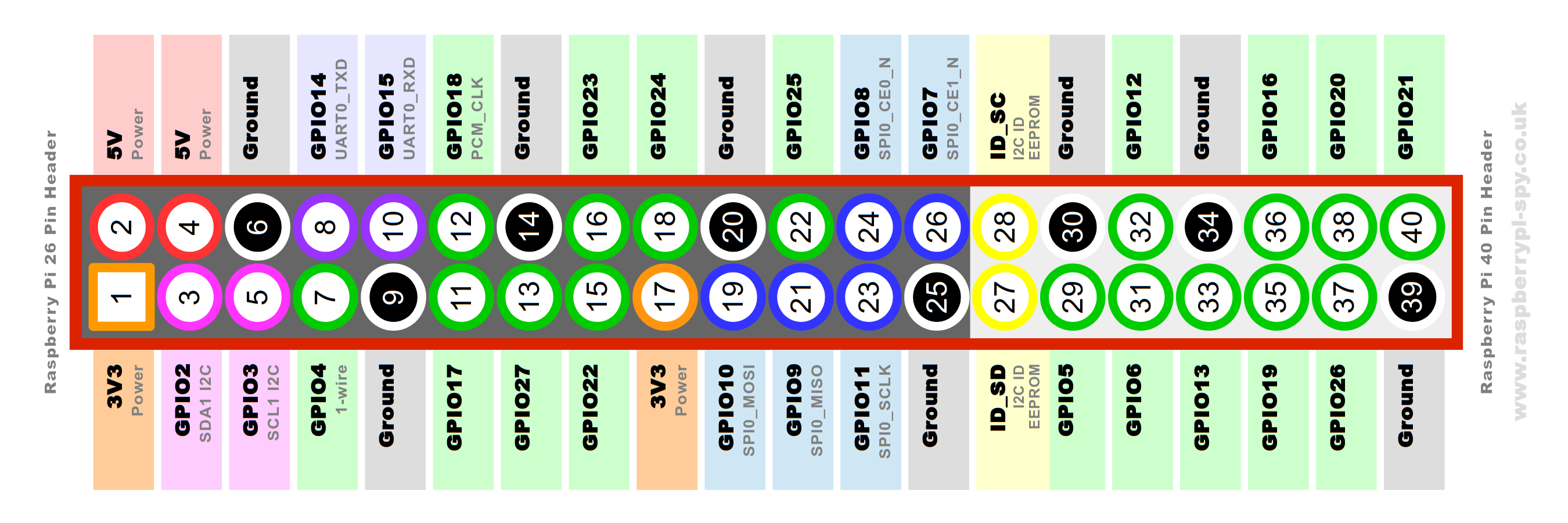
@ptvoinfo So i can use pin 6 / 8 and 10 on my pi to connect? should I not give the cc2530 power? |
|
Pins: yes, you may use 6, 8 and 10 |
|
@ptvoinfo Perfect, i will give it a try. Maybe someone can make a wiki page of this information? |
|
@1981nick1982 if you could create something basic based on your understanding, I'm happy to pimp it out with formatting and stuff |
|
I've prepared a tutorial. |
|
@ptvoinfo great work! |
|
@ptvoinfo Looks great! |
|
@ptvoinfo Super!!! i have ordered the parts. |
Great job! BTW @ptvoinfo what is the use case for the CC2530 board with additional 8051? |
|
@james-fry The additional chip implements the USB interface and the CC debugger. This board can be programmed without the debugger. Therefore it holds small space on your work table :). It can be useful for developers. If you need only one CC2530 or CC2531 for a coordinator role you may save money. |
|
Thanks. |
|
So much good information developing, thanks. Would have probably started out with the "dev-board" but I ordered exactly as per the Getting Started wiki page because I'm literal when reading instructions :) That was back in the 'old days' when the wiki was only 8 pages and there was no "Supported sniffer devices" page. Another HA user in Perth (WA) has offered to lend me his CC Debugger so maybe get something going this weekend, fingers crossed, and report in. |
|
@1981nick1982 considering the documentation now exists (thanks @ptvoinfo ) can we close this issue? |
|
Yes, it can be closed. Thank you guys. |
I intend to buy a cc2530 . However, it is not clear in the wiki how it should be flashed and how it should be connected to, for example, an RPI.
I would have liked to know which parts I have to buy to flash the CC2530. I have read this page but this does not create an overall clarity in my opinion.
If I understand correctly, I should use the pinout of this diagram to connect the CC2530 to the CC debugger / CC2531 cable? http://ptvo.info/wp-content/uploads/2018/05/smartrf04eb-pinout.jpg
And use USB to TTL - Aliexpress
for the link to the pi?
I connect this stick as follows:
TX = P0_3
RX = P0_2
RST = P0_5
GND =?
3V3 =?
5V =?
For the CC2531 there is a step by step wiki available, maybe that something similar has to be made for this solution with photos?
The text was updated successfully, but these errors were encountered: