Skip to content
New issue

Have a question about this project? Sign up for a free GitHub account to open an issue and contact its maintainers and the community.

By clicking “Sign up for GitHub”, you agree to our terms of service and privacy statement. We’ll occasionally send you account related emails.

Already on GitHub? Sign in to your account

HELP! Need help with marlin code to hook up REPRAP discount full graphic smart controller to stock Ender 3 motherboard #18225

Closed
Wiketti opened this issue Jun 8, 2020 · 27 comments

Comments

@Wiketti
Copy link

Wiketti commented Jun 8, 2020

Cant seem to get any graphics out of it.

I have added u8glib library to firmware and uncommented reprap discount full graphic smart controller from the code. Also commented ( // ) the CR-10 stock display from firmware.

It just shines blue and "whines".

@ellensp
Copy link
Contributor

ellensp commented Jun 8, 2020

This is mostly a hardware issue
2 * 10 pin plugs into 1 * 10 socket.. you can't have everything.

the reprap discount full graphics display has
encoder (3 pins)
buzzer (1 pin)
12864 lcd (3 pins)
sd card (5 additional pins)
stop button (1 pin)
power (2 pins)

So 15 pins pins going to a 10 pin plug?
This is why the CR-10 display doesn't have sdcard.

@Wiketti
Copy link
Author

Wiketti commented Jun 8, 2020

Can i modify one connector so that it matches ender's own pins without SD reader?

@ellensp
Copy link
Contributor

ellensp commented Jun 8, 2020

you have (pins numbers are reversed on some boards) (updated)
Connectors on back of RRD GLCD

 *               _____                                        _____
 *           NC | 1 2 | GND                               5V | 1 2 | GND
 *        RESET | 3 4 | SD_DETECT                     LCD_D7 | 3 4 | LCD_D6
 *         SD 2 | 5 6   BTN_EN2                       LCD_D5 | 5 6   LCD_D4
 *         SD 1 | 7 8 | BTN_EN1                       LCD_RS | 7 8 | LCD_EN
 *         SD 5 | 9 10| SD 7                         BTN_ENC | 9 10| BEEPER
 *               -----                                        -----
 *               EXP2                                          EXP1

you need to use these pins (marked with a X)

 *               _____                                        _____
 *           NC | 1 2 | GND                               5V | X X | GND
 *        RESET | X 4 | SD_DETECT                     LCD_D7 | 3 4 | LCD_D6
 *         SD 2 | 5 X   BTN_EN2                       LCD_D5 | 5 X   LCD_D4
 *         SD 1 | 7 X | BTN_EN1                       LCD_RS | X X | LCD_EN
 *         SD 5 | 9 10| SD 7                         BTN_ENC | X X | BEEPER
 *               -----                                        -----
 *               EXP2                                          EXP1

Everything with a X need to go to your 10 pin connector.
I have no idea on the wiring of that connector. but MOSI, SCK and power pins cannot be moved to other pins.

@Wiketti
Copy link
Author

Wiketti commented Jun 8, 2020

I'll give it a go soon as i get home. Thank you for the replys.

I'll get back to you as soon as i get some results.

@ellensp
Copy link
Contributor

ellensp commented Jun 8, 2020

This seems to be the connector on your controller. (please verify)

/*   EXP1 Connector       As CR10 LCD Connector
 *        _____                                   _____
 *   PA4 | 6 5 | PC0                  BEEPER_PIN | 6 5 | BTN_ENC
 *   PD3 | 7 4 | RESET                   BTN_EN1 | 7 4 | RESET
 *   PD2   8 3 | PA1                     BTN_EN2   8 3 | LCD_PINS_D4 (ST9720 CLK)
 *   PA3 | 9 2 | PC1     (ST9720 CS) LCD_PINS_RS | 9 2 | LCD_PINS_ENABLE (ST9720 DAT)
 *   GND |10 1 | 5V                          GND |10 1 | 5V
 *        -----                                   -----
 */

So if you wire to these pins and set Configuration.h LCD as a CR10_STOCKDISPLAY and cross your fingers and toes... you might get a display and working encoder, reset and buzzer.

@ellensp
Copy link
Contributor

ellensp commented Jun 8, 2020

Re check previous posts, I have updated the pins a bunch

@thisiskeithb
Copy link
Member

thisiskeithb commented Jun 9, 2020

This isn't a Marlin bug and really should be posted elsewhere as noted in the pinned "Need to ask a question?" issue, but someone has mapped out the pins & created a custom cable for a full graphic LCD on an SKR Mini E3 which uses the same EXP3/connector for a CR10_STOCKDISPLAY: bigtreetech/BIGTREETECH-SKR-mini-E3#159

image

@Wiketti
Copy link
Author

Wiketti commented Jun 9, 2020

Took me ages yesterday to make that 10 pin cable 😂 as i dont have the right crimping tool. So gonna give it a go today.

At first i just assumed it was marlin prob... 🙄 So sry to post this on wrong channel. Altho, i am super gratefull for all the help! You guys are the best!
I think i will be asking more help in near future as i'm fairly new to all this.

I'll let you know how this turns out soon 😊👌

@ellensp
Copy link
Contributor

ellensp commented Jun 9, 2020

I would have used a bunch of singe wire DuPont cables. same as you get with arduino boards and modules, then you can easily change things. Only make up a cable when you know its going to work.

@Wiketti
Copy link
Author

Wiketti commented Jun 9, 2020

They did'nt have those single duponts (or the single connectors) in the local shop 🙄 so i had to make the cable on my own. Really need to order some for future. Those arduino boards keep piling up and i dont have decent tools to go with them 😑

@Wiketti
Copy link
Author

Wiketti commented Jun 10, 2020

Okay, got those single duponts after some digging and a lot of driving 😅
Hooked the screen up like shown above (also tried reversed).

It just flickers and lights up but nothing else.

@Wiketti
Copy link
Author

Wiketti commented Jun 10, 2020

Can i link a video?

@ellensp
Copy link
Contributor

ellensp commented Jun 10, 2020

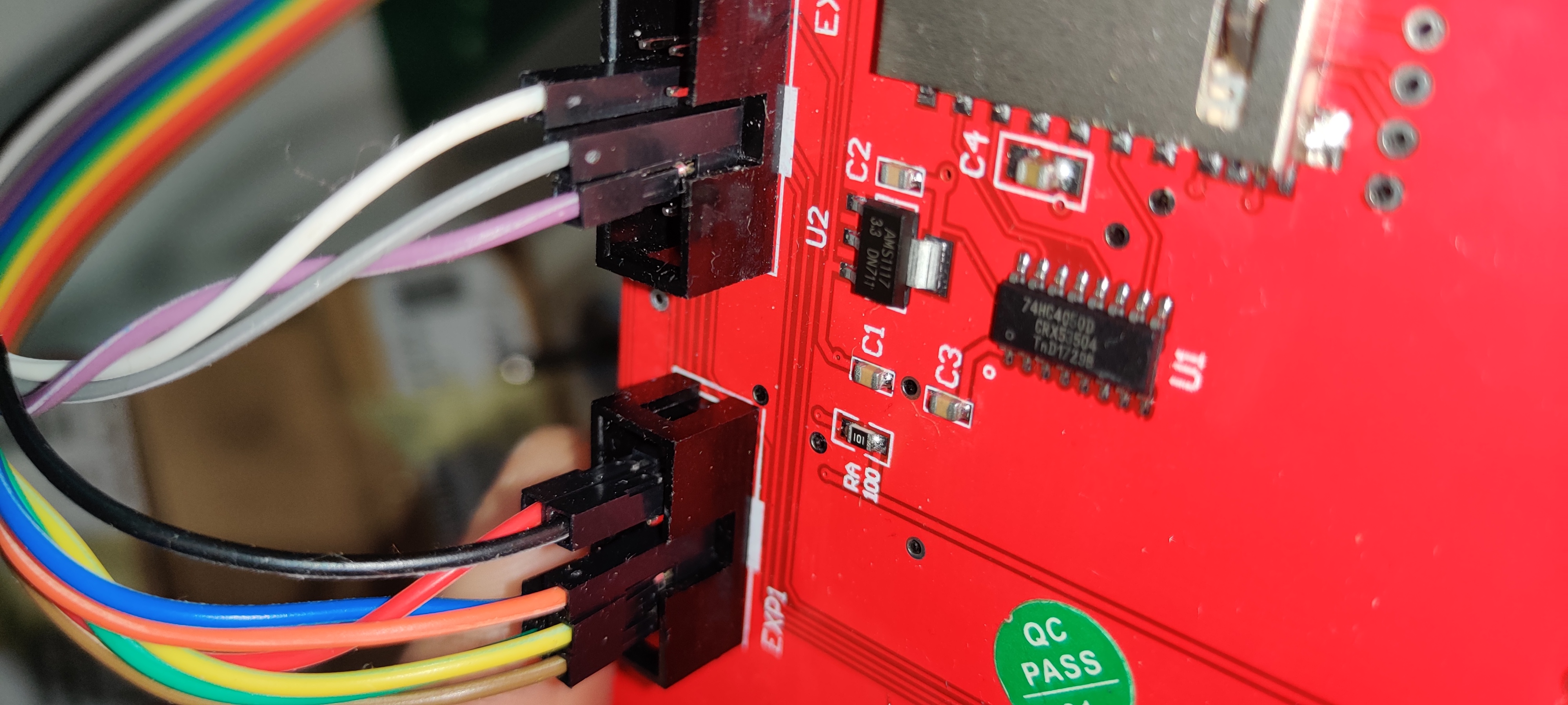
yes and images... on how you wired it, and confirm you set CR10_STOCKDISPLAY and disabled reprap discount full graphic smart controller

@ellensp
Copy link
Contributor

ellensp commented Jun 10, 2020

also do you have a multimeter... so you can confirm which pins are gnd and 5v on both ends

@Wiketti
Copy link
Author

Wiketti commented Jun 10, 2020

IMG_20200610_122932
IMG_20200610_122939
Uploading IMG_20200610_122958.jpg…

@Wiketti
Copy link
Author

Wiketti commented Jun 10, 2020

IMG_20200610_122958

@Wiketti
Copy link
Author

Wiketti commented Jun 10, 2020

do i need to install some firmware into the screen?

@ellensp
Copy link
Contributor

ellensp commented Jun 10, 2020

This https://github.com/Creality3DPrinting/Ender-3/blob/master/Ender-3%20PCB/Ender3_pcb_parts.PDF tells me that the controller is not wired correct, gnd and 5v are at other end. gnd on the inside 5v on the outside

try my pins

/*   EXP1 Connector       As CR10 LCD Connector
 *        _____                                   _____
 *   PA4 | 6 5 | PC0                  BEEPER_PIN | 6 5 | BTN_ENC
 *   PD3 | 7 4 | RESET                   BTN_EN1 | 7 4 | RESET
 *   PD2   8 3 | PA1                     BTN_EN2   8 3 | LCD_PINS_D4 (ST9720 CLK)
 *   PA3 | 9 2 | PC1     (ST9720 CS) LCD_PINS_RS | 9 2 | LCD_PINS_ENABLE (ST9720 DAT)
 *   GND |10 1 | 5V                          GND |10 1 | 5V
 *        -----                                   -----
 */

no there is no firmware on the display. its a dumb device.
firmware on the controller.

@ellensp
Copy link
Contributor

ellensp commented Jun 10, 2020

to simply things you don't need exp2 on lcd at all just yet. It is for encoder and reset pins. So you can remove those for now if you wish...

@Wiketti
Copy link
Author

Wiketti commented Jun 10, 2020

to simply things you don't need exp2 on lcd at all just yet. It is for encoder and reset pins. So you can remove those for now if you wish...

Thanks a ton! 😎👌 Really got it working 😅 took ages, but with your help i have some light in the end of the tunnel
IMG_20200610_152907
IMG_20200610_152903

Only thing that's haywire are those X,Y,Z thing going to ?,?,? From X,Y,Z

@ellensp
Copy link
Contributor

ellensp commented Jun 10, 2020

That's normal marlin, its telling you that you haven't homed the axis yet.

@Wiketti
Copy link
Author

Wiketti commented Jun 10, 2020

I´ll make decent wiring pictures and share them somewhere.(???? dont know where yet)
If someone ever would need them. Almost all controls work as they should, except extruder, cant seem to control it from prepare menu.

but i dont really care as long as i have it running now. need to do some tests before i give it thumbs up, but so far so good.

@ellensp
Copy link
Contributor

ellensp commented Jun 10, 2020

extruder needs to be hot before it will consider moving.

@Wiketti
Copy link
Author

Wiketti commented Jun 10, 2020

of course it does... silly me.

should had emmidiatly follow your guides. the pic Keith posted was not correct.

@Wiketti
Copy link
Author

Wiketti commented Jun 10, 2020

IMG-20200610-WA0008
Rough sketch but will make it better soon.

@thisiskeithb
Copy link
Member

Some of those reprap full graphic LCDs have EXP connectors that are 180 out from standard. Glad you got it working.

Since this isn’t a Marlin bug, please close the issue.

@github-actions
Copy link

github-actions bot commented Aug 9, 2020

This issue has been automatically locked since there has not been any recent activity after it was closed. Please open a new issue for related bugs.

@github-actions github-actions bot locked and limited conversation to collaborators Aug 9, 2020
Sign up for free to subscribe to this conversation on GitHub. Already have an account? Sign in.
Labels
None yet
Projects
None yet
Development

No branches or pull requests

3 participants