-
Notifications
You must be signed in to change notification settings - Fork 4
/
chapter_1-5.qmd
340 lines (248 loc) · 20.4 KB
/
chapter_1-5.qmd
1
2
3
4
5
6
7
8
9
10
11
12
13
14
15
16
17
18
19
20
21
22
23
24
25
26
27
28
29
30
31
32
33
34
35
36
37
38
39
40
41
42
43
44
45
46
47
48
49
50
51
52
53
54
55
56
57
58
59
60
61
62
63
64
65
66
67
68
69
70
71
72
73
74
75
76
77
78
79
80
81
82
83
84
85
86
87
88
89
90
91
92
93
94
95
96
97
98
99
100
101
102
103
104
105
106
107
108
109
110
111
112
113
114
115
116
117
118
119
120
121
122
123
124
125
126
127
128
129
130
131
132
133
134
135
136
137
138
139
140
141
142
143
144
145
146
147
148
149
150
151
152
153
154
155
156
157
158
159
160
161
162
163
164
165
166
167
168
169
170
171
172
173
174
175
176
177
178
179
180
181
182
183
184
185
186
187
188
189
190
191
192
193
194
195
196
197
198
199
200
201
202
203
204
205
206
207
208
209
210
211
212
213
214
215
216
217
218
219
220
221
222
223
224
225
226
227
228
229
230
231
232
233
234
235
236
237
238
239
240
241
242
243
244
245
246
247
248
249
250
251
252
253
254
255
256
257
258
259
260
261
262
263
264
265
266
267
268
269
270
271
272
273
274
275
276
277
278
279
280
281
282
283
284
285
286
287
288
289
290
291
292
293
294
295
296
297
298
299
300
301
302
303
304
305
306
307
308
309
310
311
312
313
314
315
316
317
318
319
320
321
322
323
324
325
326
327
328
329
330
331
332
333
334
335
336
337
338
339
340
# 1.5 Controlling LED and Servo with a Knob {.unnumbered}
<br />
In the last section, we learned how to use the serial monitor and observed the differences between digital input and analog input through it. In this section, we will further explore the use of analog values by combining them with a rotary potentiometer!
## 1.5.1 Background Knowledge
### 1.5.1.1 Servo and Servo Library
#### **Servo **
<!--  -->
<img src="https://files.seeedstudio.com/wiki/XIAO_Big_Power-Board-ebook-photo/chapter_1-5/chapter_1-5_1.png" alt="verify-button.png" width="300" height="auto" />
A servo, also known as a servo motor, is a DC motor with gears and a feedback system. We can control the servo to rotate to a specific angular position by sending signals to the circuit. This makes it suitable for electronic devices or robots that require precise position control.
#### **Servo Library servo.h **
When we want to control a servo using XIAO or other Arduino development boards, we can use the servo.h library file. It's one of the Arduino standard libraries, which is convenient to use and also avoids the problem of limited PWM pin quantity. Here are the relevant functions of the servo library:
- Declare the library file <br />
`#include <Servo.h>`
- Create the `myservo` object to control the servo <br />
`Servo myservo;`
- Use the `attach()` function to call the signal pin<br />
`myservo.attach();`
- Use the `write()` function to write the angle to the servo, setting the rotation angle of the shaft<br />
`myservo.write();`
The servo library does not need to be manually installed. You can open the example program **"File → Examples → Servo"** and check the two example programs "Knob" and "Sweep" to familiarize yourself with the use of the servo library.
<!--  -->

If you can't find Servo under Examples, you can visit <https://github.com/arduino-libraries/Servo> and add the Servo example by installing the library.
### 1.5.1.2 `map()` Function
The `map()` function is used to map a number from one range to another. That is, `fromLow` gets mapped to `toLow`, and `fromHigh` gets mapped to `toHigh`. It's the simplest form of linear mapping.
**Syntax** <br />
`map(value, fromLow, fromHigh, toLow, toHigh)`
**Parameters** <br />
`value`: The number to be mapped. <br />
`fromLow`: The lower limit of the current range of the value. <br />
`fromHigh`: The upper limit of the current range of the value. <br />
`toLow`: The lower limit of the target range of the value. <br />
`toHigh`: The upper limit of the target range of the value.
**Example: Map `val` from the range 0-1023 to 0-255.**
``` cpp
void setup() {}
void loop() {
int val = analogRead(0); // read the value from analog pin A0
val = map(val, 0, 1023, 0, 255); // map val to the range 0-255
analogWrite(9, val); // output the analog value to pin 9
}
```
## 1.5.2 Task 1: Using a knob potentiometer to control the brightness of the onboard LED on the XIAO board
#### **Analysis:**
When using a knob potentiometer to control the LED, we need to use the map() function, because the analog value directly output by the knob potentiometer is 0-1023, this value is not the angle value of the knob rotation, we need to calculate the angle value of the knob potentiometer rotation first, then map this value to the brightness range of the LED 0-255 with the map() function. The steps to write the program are as follows:
- Define the knob potentiometer, LED pin.
- Initialize the serial port, set the status of the knob potentiometer and LED pin.
- Read and calculate the rotation angle value of the knob potentiometer, and send it to the serial port.
- Map the angle value of the knob potentiometer to the LED brightness value and store it in the brightness variable, and the LED outputs this variable value.
#### **Writing the program**:
**Step 1:** Define the knob potentiometer, LED pin, here we need to define ADC and VCC reference voltage, in order to calculate the angle value of the knob potentiometer.
``` cpp
#define ROTARY_ANGLE_SENSOR A0 //Define rotary potentiometer interface A0
#define LEDPIN 13 //Define LED interface 13
#define ADC_REF 3 //Reference voltage 3V
#define GROVE_VCC 3 //GROVE reference voltage 3V
#define FULL_ANGLE 300 //The maximum rotation angle of the rotary potentiometer is 300°
```
**Step 2:** Initialize the serial port, set the status of the knob potentiometer and LED pin.
``` cpp
void setup()
{
Serial.begin(9600); //Initialize serial communication
pinMode(ROTARY_ANGLE_SENSOR, INPUT); //Set the rotary potentiometer pin to input
pinMode(LEDPIN,OUTPUT); //Set the LED pin to output
}
```
**Step 3:** Read and calculate the rotation angle value of the knob potentiometer, and send it to the serial port.
``` cpp
void loop()
{
float voltage; //Variable voltage of type float
int sensor_value = analogRead(ROTARY_ANGLE_SENSOR); //Read the analog value at the rotary potentiometer pin
voltage = (float)sensor_value*ADC_REF/1023; //Calculate the real-time voltage
float degrees = (voltage*FULL_ANGLE)/GROVE_VCC; //Calculate the angle of rotation of the knob
Serial.println("The angle between the mark and the starting position:"); //Print character on serial monitor
Serial.println(degrees); //Print the rotation angle value of the rotary potentiometer on the serial monitor
delay(100);
```
**Step 4:** Map the angle value of the knob potentiometer to the LED brightness value and store it in the brightness variable, and the LED outputs this variable value.
``` cpp
//After Step 3
int brightness; //Define brightness variable
brightness = map(degrees, 0, FULL_ANGLE, 0, 255); //Map the rotation angle value of the rotary potentiometer to the brightness value of the LED and store it in the brightness variable
analogWrite(LEDPIN,brightness); //Output the variable value to the LED
delay(500);
}
```
The final complete code is shown below:
``` cpp
#define ROTARY_ANGLE_SENSOR A0 //Define rotary potentiometer interface A0
#define LEDPIN 13 //Define LED interface 13
#define ADC_REF 3 //Reference voltage 3V
#define GROVE_VCC 3 //GROVE reference voltage 3V
#define FULL_ANGLE 300 //The maximum rotation angle of the rotary potentiometer is 300°
void setup()
{
Serial.begin(9600); //Initialize serial communication
pinMode(ROTARY_ANGLE_SENSOR, INPUT); //Set the rotary potentiometer pin to input
pinMode(LEDPIN,OUTPUT); //Set the LED pin to output
}
void loop()
{
float voltage; //Variable voltage of type float
int sensor_value = analogRead(ROTARY_ANGLE_SENSOR); //Read the analog value at the rotary potentiometer pin
voltage = (float)sensor_value*ADC_REF/1023; //Calculate the real-time voltage
float degrees = (voltage*FULL_ANGLE)/GROVE_VCC; //Calculate the angle of rotation of the knob
Serial.println("The angle between the mark and the starting position:"); //Print character on serial monitor
Serial.println(degrees); //Print the rotation angle value of the rotary potentiometer on the serial monitor
delay(100);
int brightness; //Define brightness variable
brightness = map(degrees, 0, FULL_ANGLE, 0, 255); //Map the rotation angle value of the rotary potentiometer to the brightness value of the LED and store it in the brightness variable
analogWrite(LEDPIN,brightness); //Output the variable value to the LED
delay(500);
}
```
> Get this program from Github <br />
> <https://github.com/mouseart/XIAO-Mastering-Arduino-and-TinyML/tree/main/code/L5_RotaryLed_XIAO_en>
#### **Uploading the Program:**
After writing the program, connect the rotary potentiometer to the `A0` interface using a four-color Grove wire, as shown in the following figure:
<!--  -->

Connect the XIAO main control board to your computer with a data cable. After connecting, click <img src="https://files.seeedstudio.com/wiki/XIAO_Big_Power-Board-ebook-photo/verify-button.png" alt="verify-button.png" width="30" height="30" /> (the verify button) in the Arduino IDE to check the program. If there are no errors, click <img src="https://files.seeedstudio.com/wiki/XIAO_Big_Power-Board-ebook-photo/upload-button.png" alt="upload-button.png" width="30" height="30" /> (the upload button) to upload the program to the hardware. When the debug area shows "Done uploading.", you can open the serial monitor to observe the rotation angle and LED brightness values as you rotate the potentiometer.
<!--  -->

> ⚠️ Note <br />
> The onboard LED of the XIAO board is used in this example.
If you need to operate offline, you can connect a lithium battery to the expansion board, as shown in the following figure.
<!--  -->

### Controlling an External LED with a Knob on the XIAO ESP32C3
The Seeed XIAO ESP32C3 does not have an onboard LED for users. To run this program, you need to first connect an LED to the `D10` pin of the board, as shown below:
<!--  -->
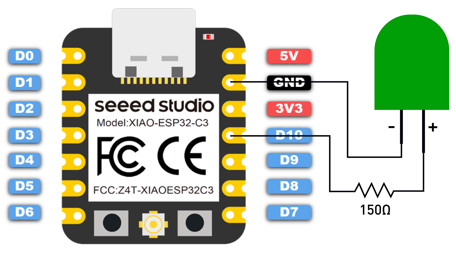
> ⚠️ Note <br />
> Be sure to connect a resistor (about 150Ω) in series with the LED to limit the current passing through the LED and prevent it from being damaged by overcurrent.
Next, copy the following program into the Arduino IDE:
``` cpp
#define ROTARY_ANGLE_SENSOR A0 // Define rotary potentiometer interface A0
#define LEDPIN D10 // Define LED light interface 10
#define ADC_REF 3 // Reference voltage 3V
#define GROVE_VCC 3 // GROVE reference voltage 3V
#define FULL_ANGLE 300 // The maximum rotation angle of the rotary potentiometer is 300°
void setup()
{
Serial.begin(9600); // Initialize serial communication
pinMode(ROTARY_ANGLE_SENSOR, INPUT); // Set the rotary potentiometer pin to input mode
pinMode(LEDPIN, OUTPUT); // Set the LED light pin to output mode
}
void loop()
{
float voltage; // Define voltage variable as float
int sensor_value = analogRead(ROTARY_ANGLE_SENSOR); // Read the analog value on the rotary potentiometer pin
voltage = (float)sensor_value*ADC_REF/1023; // Calculate real-time voltage
float degrees = (voltage*FULL_ANGLE)/GROVE_VCC; // Calculate the angle of rotation of the knob
Serial.println("The angle between the mark and the starting position:"); // Print string to serial port
Serial.println(degrees); // Print the rotation angle value of the rotary potentiometer to the serial port
delay(100);
int brightness; // Define brightness variable
brightness = map(degrees, 0, FULL_ANGLE, 0, 255); // Map the rotary potentiometer angle value to LED light brightness value and store it in the brightness variable
analogWrite(LEDPIN, brightness); // Output brightness value to LED light
delay(500);
}
```
> Get this program from Github <br />
> <https://github.com/mouseart/XIAO-Mastering-Arduino-and-TinyML/tree/main/code/L5_RotaryLed_XIAO_ESP32C3_en>
## 1.5.3 Task 2: Control a Servo Motor with a Rotary Potentiometer
#### **Analysis**
When controlling a servo motor with a rotary potentiometer, we can use the `servo.h` library and modify our first task slightly. The program can be divided into the following steps:
- Declare the servo library, define the servo rotation angle variable, define the rotary potentiometer pin and voltage.
- Initialize the serial port, set the status of the rotary potentiometer and servo pins.
- Read and calculate the rotation angle value of the rotary potentiometer, send it to the serial port, and drive the servo to rotate according to the angle value change.
#### **Program Writing **
**Step 1:** Declare the servo library, define the servo rotation angle variable, define the rotary potentiometer pin and voltage.
``` cpp
#include <Servo.h>// Declare the use of the servo library
#define ROTARY_ANGLE_SENSOR A0 // Define the rotary potentiometer pin as A0
#define ADC_REF 3 // ADC reference voltage is 3V
#define GROVE_VCC 3 // GROVE module reference voltage is 3V
#define FULL_ANGLE 300 // The maximum rotation angle of the rotary potentiometer is 300°
Servo myservo; // Create a myservo object to control the servo
int pos = 0; // Variable to store the rotation angle of the servo
```
**Step 2:** Initialize the serial port, set the status of the rotary potentiometer and servo pins.
``` cpp
void setup() {
Serial.begin(9600);// Initialize the serial port
pinMode(ROTARY_ANGLE_SENSOR, INPUT);// Set the rotary potentiometer pin as input
myservo.attach(5); // The myservo signal is transmitted through pin 5, if you are using XIAO RP2040/XIAO ESP32, please modify 5 to D5
}
```
**Step 3:** Read and calculate the rotation angle value of the rotary potentiometer, send it to the serial port, and drive the servo to rotate according to the angle value change.
``` cpp
void loop() {
float voltage;// Set voltage as a floating point
int sensor_value = analogRead(ROTARY_ANGLE_SENSOR);// Read the analog value at the rotary potentiometer pin
voltage = (float)sensor_value * ADC_REF / 1023;// Real-time voltage is the read analog value multiplied by the reference voltage divided by 1023
float degrees = (voltage * FULL_ANGLE) / GROVE_VCC;// The rotation angle of the knob is the real-time voltage multiplied by the maximum rotation angle of the rotary potentiometer divided by the voltage value of the GROVE module interface
Serial.println("The angle between the mark and the starting position:");// Print characters on the serial port
Serial.println(degrees);// Print the rotation angle value of the rotary potentiometer on the serial port
delay(50);
myservo.write(degrees); // Write the rotation angle value of the rotary potentiometer into the servo
}
```
The final code is as follows:
``` cpp
#include <Servo.h>// Declare the use of the servo library
#define ROTARY_ANGLE_SENSOR A0 // Define the rotary potentiometer pin as A0
#define ADC_REF 3 // ADC reference voltage is 3V
#define GROVE_VCC 3 // GROVE module reference voltage is 3V
#define FULL_ANGLE 300 // The maximum rotation angle of the rotary potentiometer is 300°
Servo myservo; // Create a myservo object to control the servo
int pos = 0; // Variable to store the rotation angle of the servo
void setup() {
Serial.begin(9600);// Initialize the serial port
pinMode(ROTARY_ANGLE_SENSOR, INPUT);// Set the rotary potentiometer pin as input
myservo.attach(5); // The myservo signal is transmitted through pin 5, if you are using XIAO RP2040/XIAO ESP32, please modify 5 to D5
}
void loop() {
float voltage;// Set voltage as a floating point
int sensor_value = analogRead(ROTARY_ANGLE_SENSOR);// Read the analog value at the rotary potentiometer pin
voltage = (float)sensor_value * ADC_REF / 1023;// Real-time voltage is the read analog value multiplied by the reference voltage divided by 1023
float degrees = (voltage * FULL_ANGLE) / GROVE_VCC;// The rotation angle of the knob is the real-time voltage multiplied by the maximum rotation angle of the rotary potentiometer divided by the voltage value of the GROVE module interface
Serial.println("The angle between the mark and the starting position:");// Print characters on the serial port
Serial.println(degrees);// Print the rotation angle value of the rotary potentiometer on the serial port
delay(50);
myservo.write(degrees); // Write the rotation angle value of the rotary potentiometer into the servo
}
```
> Get this program from Github <br />
> <https://github.com/mouseart/XIAO-Mastering-Arduino-and-TinyML/tree/main/code/L5_RotaryServo_XIAO_en>
------------------------------------------------------------------------
#### **Upload Program**
After writing the program, first connect the knob potentiometer and the servo to the XIAO expansion board as shown in the figure below. Then, connect the XIAO main control board to the computer with a data cable.
<!--  -->

After the connection, click <img src="https://files.seeedstudio.com/wiki/XIAO_Big_Power-Board-ebook-photo/verify-button.png" alt="verify-button.png" width="30" height="30" />(the verify button) in the Arduino IDE to verify the program. If the verification is error-free, click <img src="https://files.seeedstudio.com/wiki/XIAO_Big_Power-Board-ebook-photo/upload-button.png" alt="upload-button.png" width="30" height="30" /> (the upload button) to upload the program to the hardware. When the debugging area shows "Done uploading.", you can open the serial monitor, rotate the knob potentiometer, and observe the changes in angle value and the movement of the servo. What have you found?
<!--  -->

> ⚠️ Note <br />
>The rotation range of the servo is 0°-180°, so you will see in the serial monitor that when the angle value is greater than 180°, the servo stops rotating.
## 1.5.4 Extended Exercise
We have been using the LED on the XIAO board. If I want to use an external LED and control it with a knob potentiometer to create a breathing light effect, what should I do? The XIAO expansion board brings out two digital-analog Grove interfaces, and there is an `A7/D7` interface. We can connect the external LED to this interface, as shown in the figure:
<!--  -->

After the connection, we can slightly modify the program from Task 1, changing `#define LEDPIN 13` to `#define LEDPIN 7`. Upload the modified program and see if it can achieve our desired effect.
> Get this program from Github <br />
> <https://github.com/mouseart/XIAO-Mastering-Arduino-and-TinyML/tree/main/code/L5_RotaryLed_ledmodule_en>