Mycroft's Mark II Raspberry Pi 3 based prototype designs
*⛵️ This design is not longer offcially supported by Mycroft *

- Copy our designs – build your own Mycroft Mark 2 - Raspberry Pi Edition or its individual parts
- Modify our designs – remixing is encouraged
- Sell products based on our designs – commercial use is permitted
- Always keep the open license – contribute your output back to the community
- Credit the original author(s) – like they do in science
We're open-sourcing all our designs under the CERN Open Hardware License, which is one of the open hardware licenses recommended by OSHWA, the Open Source Hardware Association. The release involves every single piece of our design except components we have no control over, like the Raspberry Pi. We've also joined the Open Source Hardware Certification Program.

To begin you need to purchase the parts listed in the Bill of Materials (BOM). The Mark II Raspberry Pi 3 prototype consists of 7 major components and many smaller components needed to connect them together. The 7 major components are:
- Raspberry Pi 3B (not 3B+ or 4 yet)
- Seeed Studios Respeaker Mic Array v2.0
- Waveshare 4.3" IPS 800x480 LCD
- Drok 12v to 5v 5A buck converter part # 200217
- Adafruit 20W Stereo class D Amplifer - MAX9744
- A pair of Tymphany Peerless TC5FC07-04 speaker drivers
- A set of 3D printed Mark II Raspbery Pi 3 prototype parts

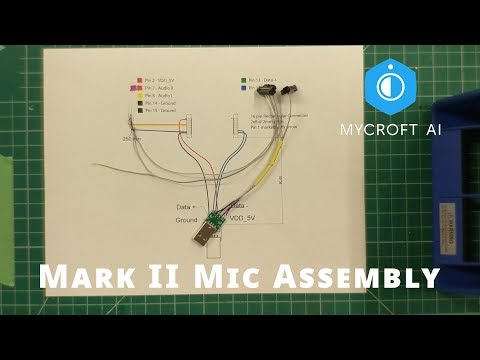
To connect the Raspberry Pi, Respeaker Mic Array V2.0, and Adafruit Amplifer two custom cable assemblies are required. The first cable assembly allows the Respeaker Mic Array to communicate to the Raspberry Pi via USB and to the Amplifer via analog stereo audio. To create the Microphone cable assembly follow this video guide:
The second cable assembly connects the i2c interface from the GPIO on the Raspberry Pi to the Adafruit amplifier. This allows the Raspberry Pi to digitally control the gain on the amplifier. To create the GPIO to i2c cable assembly follow this video guide:
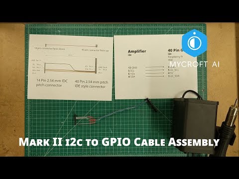
The connectors and ribbon cables required to build both of these cable assemblies are listed in the BOM.
The parts for the housing are shared as both STL and STP files under CAD. Our prototypes are printed on a Formlabs SLA 3D printer but these can be adapted for printing on an FFF machine as well. You will need to orient the parts and slice them based on the requirements of your printer. Some parts require the additoin of threaded inserts for assembly. Two sizes of threaded inserts are used in the prototype m2.5 and m2. These can be installed in the parts with a soldering iron if using FFF printing, or with Cyanoacrylate glue (super glue) if you're using an SLA printer. SLA printed parts do not melt like FFF parts so installation with a soldering iron won't work. These images show the size and location of the threaded inserts threaded insert locations
Follow this guide on Adafruit's website to assemble the amplifier. Soldering skills are needed. You will also need to solder leads onto the Tymphany speaker drivers. There is a small dot marking the positive side of the speaker. It is important that you wire the speakers correctly or they will be out of phase. Use the red 22 gauge wire for positive and the black for negative.
The audio chamber is printed in two parts and glued together with hot glue. The Tymphany drivers are installed on either side of the Audio chamber and the wires go through holes in the back to allow for easy connection to the speaker terminals on the amplifier. Install the Amplifer to the back of the Audio Chamber with 4 m2x6mm screws.
A video is coming soon. Connect the Raspberry Pi3 to the Waveshare display with the Waveshare included stand-offs. Connect the HDMI to HDMI connector (included with Waveshare display) and USB-A to MicroUSB connector (included with the Waveshare display) to the Rpi3 and the display. Install the Waveshare display and Rpi3 assembly through the front facing side of the Front Piece. It is a tight squeeze so you will need to angle the display to get it in. The ports should be facing up. Secure the display with 4 m2.5x6mm screws through the 4 L-shaped brackets. Attach the two Body pieces to the threaded inserts on the Front Piece. Next attach the the Drok Power Supply to the Base. The barrel connector should line up with a hole in the base. Plug the Cerrxian USB-A to MicroUSB cable into the USB port on the Drok. Attach a MicroUSB cable with positive and negative leads to the terminal next to the USB port on the Drok power converter. Next hot glue the SD Card extension behind the Drok Power Converter so that it is facing down and the MicroSD card slot will be accessible from the bottom of the device. Bring the Body/Front Piece assembly and Base together and plug the MicroSD card extension into the Rpi3. Now attach the Base to the Body and Front Piece assembly via 4 m2.5x10mm screws through the holes in the base of the Mark II. Attach the Respeaker Mic Array v2.0 to the Top-2 with 3 m2x4mm screws. Attach the Top-2 and Mic Array assembly to the Top piece with 4 m2x6mm screws. Attach the Microphone Cable Assembly to the bottom of the Respeaker Mic Array. Plug the USB into the Raspberry Pi, and slide the assembled Microphone Array and Top into the slots at the top of the Body. Attach the i2c Cable Assembly to the Raspberry Pi 3. Install the Audio Chamber onto the 4 screw bosses on the Body. The Audio Chamber won't be secure until the Back is installed. Placing the Mark II face down on a soft surface at this point is probably the easiet for installation. Connect the 12v terminal on the Drok power converter to the 12v terminal on the Amplifier with red and black 22 gauge wire. Connect the 3 audio cables from the Mic Cable Assembly to the L, N, R terminals on Amplifier. Now install the back piece through the Audio Chamber and secure it to the Body. The Mark II prototype assembly is now complete.
We still need to release the GUI prototype software, but once the software is relased, download the image burn it to a 16gb or larger SD card with Etcher and plug it into the bottom of the Mark II. Plug in the power supply and follow the instructions.
If you are doing, or planning to do, something interesting with our designs, or if you just have a question regarding the files, get in touch with our Chief of Design Derick! (He was the one who designed Mycroft Mark II’s enclosure.)

Derick Schweppe
Mycroft AI’s Chief of Design
derick.schweppe@mycroft.ai