| title | category | bzurl | oldwikiname | prodimagename | surveyurl | sku | tags |
|---|---|---|---|---|---|---|---|
Grove - Sound Sensor |
Sensor |
Grove_-_Sound_Sensor |
page.jpg |
101020023 |
io_3v3, io_5v, plat_duino, plat_linkit, plat_bbg, plat_wio, plat_pi, plat_linkit |

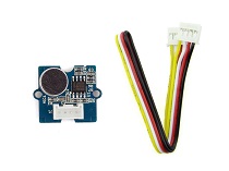
Grove - Sound Sensor can detect the sound intensity of the environment. The main component of the module is a simple microphone, which is based on the LM386 amplifier and an electret microphone. This module's output is analog and can be easily sampled and tested by a Seeeduino.
![]()
- Easy to use
- Provides analog output signal
- Easily integrates with Logic modules on the input side of Grove circuits
!!!Warning This sound sensor is used to detect whether there's sound surround or not, please don't use the module to collect sound signal. For example, you can use it to make a sound control lamp, but not as a recording device.
| Item | Value |
|---|---|
| Operating Voltage Range | 3.3/5 V |
| Operating Current(Vcc=5V) | 4~5 mA |
| Voltage Gain(V=6V, f=1kHz) | 26 dB |
| Microphone sensitivity(1kHz) | 52-48 dB |
| Microphone Impedance | 2.2k Ohm |
| Microphone Frequency | 16-20 kHz |
| Microphone S/N Radio | 54 dB |
!!!Tip More details about Grove modules please refer to Grove System
| Arduino | Raspberry Pi | BeagleBone | Wio | LinkIt ONE |
|---|---|---|---|---|
!!!Caution The platforms mentioned above as supported is/are an indication of the module's hardware or theoritical compatibility. We only provide software library or code examples for Arduino platform in most cases. It is not possible to provide software library / demo code for all possible MCU platforms. Hence, users have to write their own software library.
!!!Note If this is the first time you work with Arduino, we firmly recommend you to see Getting Started with Arduino before the start.
Hardware
- Step 1. Prepare the below stuffs:
| Seeeduino V4.2 | Base Shield | Grove-Sound Sensor |
|---|---|---|
 |
 |
 |
| Get One Now | Get One Now | Get One Now |
- Step 2. Connect Grove-Sound Sensor to port A0 of Grove-Base Shield.
- Step 3. Plug Grove - Base Shield into Seeeduino.
- Step 4. Connect Seeeduino to PC via a USB cable.

!!!Note If we don't have Grove Base Shield, We also can directly connect Grove-LED Bar to Seeeduino as below.
| Seeeduino | Grove-Sound Sensor |
|---|---|
| 5V | Red |
| GND | Black |
| A1 | White |
| A0 | Yellow |
Software
- Step 1. Please copy below code to Arduio IDE and upload to arduino. If you do not know how to upload the code, please check how to upload code.
// test code for Grove - Sound Sensor
// loovee @ 2016-8-30

const int pinAdc = A0;

void setup()
{
    Serial.begin(115200);
    //Serial.println("Grove - Sound Sensor Test...");
}

void loop()
{
    long sum = 0;
    for(int i=0; i<32; i++)
    {
        sum += analogRead(pinAdc);
    }

    sum >>= 5;

    Serial.println(sum);
    delay(10);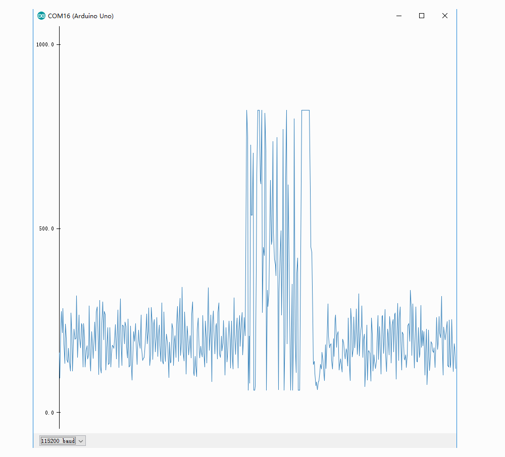
}- Step 2. Click on Serial > Plotter to get the changing curve of the sensor. Please make a noise to view the change of the value.
Hardware
- Step 1. Prepare the below stuffs:
| Raspberry pi | GrovePi_Plus | Grove-Sound Sensor | Grove-White LED |
|---|---|---|---|
 |
 |
|
 |
| Get One Now | Get One Now | Get One Now | Get One Now |
-
Step 2. Plug the GrovePi_Plus into Raspberry.
-
Step 3. Connect Grove-Sound Sensor Bar to D5 port of GrovePi_Plus.
-
Step 4. Connect the Raspberry to PC through USB cable.

- Schematic and PCB in Eagle format
- Schematic in PDF format
- PCB in PDF format
- Github Page of this Document
- LM386.PDF
Please do not hesitate to contact techsupport@seeed.cc if you have any technical issue. Or submit the issue into our forum.