[Q] Modbus and push button on C0135 #238
Comments
|
Hi :-) There are plans to implement the MODBUS RTU protocol. My problem has been creating a test setup. Is my understanding right that you're talking about a MODBUS endpoint based on the C0135 board and not a MODBUS master? Otherwise, what's the role of Forth (e.g. local logic, fallback-behavior)? |
|
Thanks for your response! Lets me describe the problem I want to solve: From what I know INT1-4 are read only by default on C0135 (I don't have C0135 yet).
|
|
I browsed the openHAB MODBUS docs: what surprised me is that there doesn't seem to be the notion of a bus, just that of a MODBUS device connected to an RS485 interface with specific parameters (otherwise it looks like a nice piece of software!). If that's the case (please check!) two C0135 devices would have to be connected to two independent RS485 buses. Otherwise a solution might be to build something using cheap Chinese modules (e.g. 8 relay board, RS485 converter, STM8S103F3P6 module), a couple of resistors and diodes for the inputs, some perfboard, and wires. Now we come to the software: I've not yet done it but I guess that the implementation of the MODBUS RTU protocol isn't too hard if one has an example and a cheap protocol analyzer (the latter I have). I wanted to implement a UART interrupt handler anyway. What I don't know is if the MODBUS implementation on the openHAB side tolerates some delay when sending RTU replies. |
|
wow, thanks for such great analisis! |
|
Ok then - give me some time - maybe I can hack a MODBUS RTU implementation during the Christmas break :-) |
|
Ok, the Modicon Modbus Protocol Reference Guide PI–MBUS–300 Rev. J contains the most useless description of a binary encoding I've ever seen: I double checked: no, the MODBUS RTU protocol doesn't use "two hexadecimal characters" for "each 8-bit byte in a message": This information about timing constraints is relevant: Regarding endianness I found more information about magic of hexadecimal numbers. However, I infer that RTU is big-endian: |

|
FYI, Realterm can encode messages with modbus16 crc, on the "send" tab This might help you verify. |
|
Thanks, that's cool I'll have to "steal" my wife's laptop computer, though - maybe I should somehow get a Windows10 machine for such tests. |
|
Here is the module source, for what its worth (I always find a specific numeric example useful): |
|
I'm using HEX
\ All light: 01 06 00 01 ff ff d9 ba (vendor's MODBUS RTU docs )
-1 $01 CRC16 $06 CRC16 $00 CRC16 $01 CRC16 $FF CRC16 $FF CRC16 . BAD9 ok
\ 1 3 0 $7E 0 10 = A5 D5 -good (old and new)
-1 $01 CRC16 $03 CRC16 $00 CRC16 $7E CRC16 $00 CRC16 $0A CRC16 . D5A5 ok
\ 1 3 0 $81 0 10 = 95 E5 - good ; 3F E5 - bad
-1 $01 CRC16 $03 CRC16 $00 CRC16 $81 CRC16 $00 CRC16 $0A CRC16 . E595 okLooks good :-) Oh, it's been a while since I coded in Turbo Pascal 6 or Borland Pascal 7 - I used to earn my salary with that :-D My humble routine looks like this: : CRC16 ( n c -- n )
\ CRC-16-ANSI (seed with -1 for Modbus CRC)
XOR DOXCODE [
$A608 , \ LD A,#8
$54 C, \ 1$: SRLW X
$2407 , \ JRNC 2$
$01 C, \ RRWA X ; XOR X,#0xA001
$A801 , \ XOR A,#0x01
$01 C, \ RRWA X
$A8A0 , \ XOR A,#0xA0
$01 C, \ RRWA X
$4A C, \ 2$: DEC A
$26F3 , \ JRNE 1$
] ;43 bytes including header, no variables :-) |
|
Interrupt driven RxD was easy. I also have the "3.5 character time" trigger for processing in the slave working. The processing runs in the idle task - not sure if that's the right place to put it but it's very convenient for debugging. Let's see how the next steps will look like. |
|
I ran into a problem: the CRC16 test with various examples was successful (see above). Now I tested processing of received messages with the command line tools mbpoll and modbus-cli. Both programs send a different CRC value than I expected:
Something isn't quite right. |
|
The current code is here: https://gist.github.com/TG9541/25a0d8e2e68e42d08ecec13c7e9a9981 I'm using a STM8S103F3P6 breakout board and the DOUBLECOM binary. |
|
The examples here are correct: CRC high and low bytes have to be swapped (little endian): This is the example: This leaves us with two types of MODBUS masters... What am I missing here? |
|
This thread warrants social studies. @bademux I'll need your input here. Please provide logs from openHAB MODBUS :-) |
|
@TG9541 thanks for research. |
|
@bademux : I've assumed that we use MODBUS RTU as it appears to be much more popular than MODBUS ASCII. The jamod link you provided describes what kind of problems are to be expected when using that implementation (the 1.5 Character Time upper bound for serial transmission inter character delay is maybe problematic for anything that's JAVA based). The best way to proceed, I guess, is to actually use openHAB to produce MODBUS RTU requests. |
|
@bademux helped me to locate the problem: there is nothing wrong with openHAB/JAMOD or Python libmodbus (mbpoll and modbus-cli): the problem was that The MODBUS reveive Gist has been updated! |
|
I've got bidirectional communication with ISR chains and RS485 access control working. STM8 UART TX handlers are a bit peculiar. The gist is here. |
|
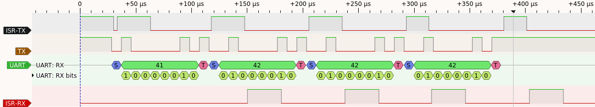
I tested the timing of the
The diagram shows nicely how the TX ISR chain works (double load at spin-up 30µs, spin-down and end-of-transmission 20µs). The RX ISR also takes about 30µs for copying a char to the receive buffer and writing the receive time stamp including buffer bounds checking. My conclusion is that buffered communication with ISRs in STM8 eForth is good up to 115200 baud in full-duplex mode and up to 230400 baud in half duplex mode (e.g. MODBUS). Higher baud rates require optimizations, e.g. assembly instead of the Forth VM for control structures and data flow. |
|
for simle usecases like on\off switches it is more than enough. |
|
@bademux: that's good progress but we're not there yet :-) Which MODBUS features will we need (e.g. supported MODBUS function codes, MODBUS registers in EEPROM)? I can see that for the on/off-switches we'll need some kind of "fail-safe properties" (e.g. how to detect when the MODBUS master is down, how manipulate states locally). When there are local states we also need to establish a protocol for state information synchronization by the MODBUS master when the connection is active again. |
|
Yes it is good progress. In case of faliure Modbus master reread register one again. |
|
This sounds good! Users will observe an immediate reaction, and automation use cases can be handled by the MODBUS master nevertheless. States can even be stored in local EEPROM. |
|
Maybe it is better to store states in RAM? |
|
First light with MBTEST: My test code MBTEST outputs the following: This only works for FC 16 but at least it works :-) The test code runs in an I also updated UARTISR. |
|
Now it also works with the JAMOD SerialDITest: The STM8 eForth console output is this: I updated MBTEST. MODBUS has a way to keep a programmers busy by using 1 and 0 as index for the first element in a seemingly random way. Edit: I guess that an implementation for an 8bit µC with 8K Flash will be allowed certain implementation gaps (e.g. reject input indices that are not multiples of 8, and always serve 8 inputs per byte). It's not like we're building a generic standard compliant product, and something will go terribly wrong because we don't know how to use it, right? |
|
|

|
Here is something I'd like to come back to:
I think it's possible to create a distributed MODBUS slave, that is a number of nodes on the same bus that interpret the register address as an extended node identification. These would only answer to input, coil and holding r/w which they are responsible for. The shared bus would allow for a distributed error reaction when none of the nodes that share a MODBUS ID sends a regular response. |
Absolutely right - minimal working implementation is one we need.
I know that modbus allows to have several slave devices identified by their addresses. |
|
JAMOD didn't provide a CLI test for MODBUS RTU FC01 "Read Coils" and FC05 "Write Single Coils" so I did some copy-and-paste programming:
I updated MBTEST and implemented FC01 (Read Coils) and FC05 (Write Single Coil). Here is the test result: |
|
I did a test with the original relay board firmware. The programmer didn't care about the timing requirements, or didn't bother reading the protocol specification: Another observation: the FC02 "Read Discrete Inputs" implementation is quirky: The response should, of course, have been Another observation: the inputs are low-side (or "NPN" as the automation people say). That makes sense since switches can be connected directly. One should, however, be careful with of-the-shelf inductive sensors for automation: a disconnect of the sensor ground may destroy the µC on the board. Some more observations:
|

|
Here is a general MODBUS protocol handler with the following features:
By the way: there must be a bug in JAMOD: it doesn't take "no" for an answer. MBPOLL handles exception codes correctly, so I don't think that the problem is at my side. |
|
Next step, here is a (very simple) MODBUS server implementation that handles FC01 and FC05 (and that has dummies for FC02 and FC16). The implementation works but some more factoring would be beneficial, and exception codes, e.g. for out-of-range parameters, should be implemented. That shouldn't be a big problem, though: the complete MODBUS server (including protocol and buffered UART) currently fits in 1341 bytes Flash memory: in SWIMCOM there is still 2007 bytes free. |
|
I updated UARTISR: the baud rate is now selectable from 2400 to 230400 baud. |
|
I factored out the basic processing of the core FCs functional programming style: \ process MB in (xt) steps with bpu bit per increment
: mbreply ( xt bpu -- )
mbp2 * 1- 8 / 1+ txc+
mbp1 mbp2 OVER + SWAP DO
( xt ) I OVER EXECUTE ( inc )
+LOOP
DROP
;The reply loop "mbp2 units starting from mbp1 with bpu bits per unit" gets loop increments inc from the access function that's passed in as xt (execution token, in STC Forth a code address). This way at least FC01, FC02, FC03 and FC04 can be implemented with just describing core functionality: :NVM ( i -- 1 ) \ FC03 holding register transfer
2* holding + @ tx+
1 ( inc )
;RAM ( xt ) NVM
\ FC03 handler "Read Holding Registers"
: FC03 ( -- )
( xt ) LITERAL 16 ( xt bpu ) mbreply
; For now I only allow bit addressed FCs with byte-aligned start addresses. Changing that shouldn't be too difficult. :NVM ( i -- 8 ) \ FC01 coils register transfer
8 / coils + 1 XOR ( BE -> LE ) @ txc+
8 ( inc )
;RAM ( xt ) NVM
\ FC01 handler "Read Coils"
: FC01 ( -- )
( xt ) LITERAL 1 ( xt bpu ) mbreply
;Mapping functionality to FCs is now reduced to assigning a "bit per unit" value and a "loop action" execution token for the copy function. The handler can then take care of plausibility tests. I think that with minor modifications the method can also be used to implement write operations like FC15, FC16 and to read-write FC23. |
|
The main functionality is now implemented with working handlers for FC01, FC02, FC03, FC04, FC05, FC15 and FC16. The code is really dense but, as I think, very maintainable. The MODBUS server (including buffered UART ISR routines) requires less than 400 lines of code and 1365 bytes of Flash memory (with 1983 bytes free). I used SWIMCOM, which is a "full featured" STM8 eForth binary - a custom binary for MODBUS could be smaller by at least 600 bytes. What's still missing is range checks (and the evaluating the MODBUS server ID ;-) ). Not a biggie, maybe 20 lines of code and less than 200 bytes of Flash memory. In any case, there is plenty of space for any kind of application software software, and maybe also for a console with a MODBUS compatible transport. I should better open a repository for that :-) |
|
MODBUS is work in proress feature as for now. |
|
There is now a GitHub repository for MODBUS with STM8 eForth! |
Hello,
I'm looking for easy way control relay (220V load) with modbus and input pins (push buttons) on C0135 board.
As far as I understand I need to implement modbus and handling push buttons with GPIO?
Is it possible\worth with stm8ef?
Thanks for great project.
The text was updated successfully, but these errors were encountered: