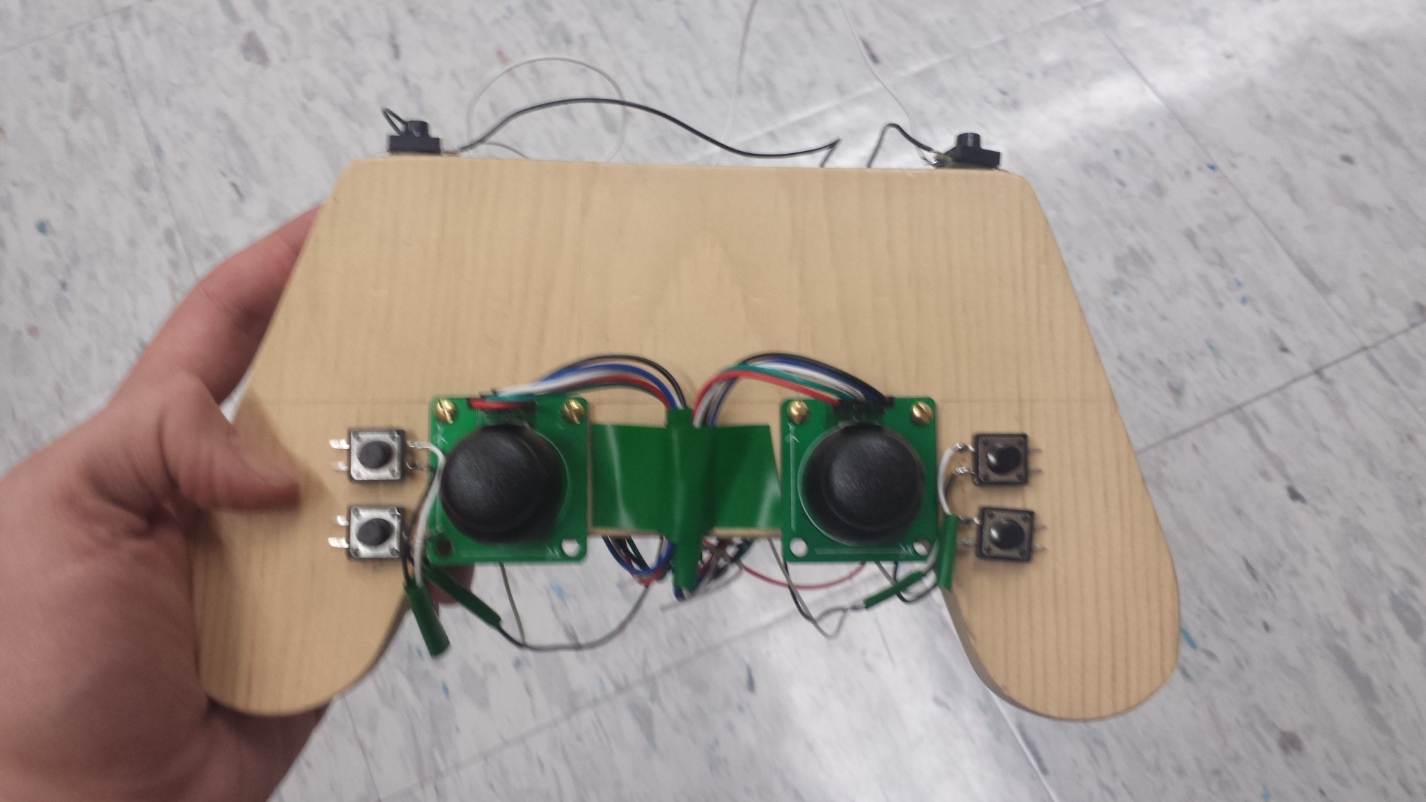
In this lab I wrote the firmware for the fully functional video game controller I built last week in Lab 01. Additionally, some of the extra parts I ordered from the internet have begun to come in so I have began doing some testing with those. Next week, for Lab 03, I will modify game engines to gather statistical data about the effectiveness of this controller. I will outline future improvements in the Conclusion.
Pictures corresponding with this lab report can be found here!
At this time, my controller is still in the same state it was last week since I am still experimenting with the new parts that came in over the last week. To recall, at the moment my controller is equipped with the following hardware:
- Arduino Micro
- Tactile Switches (x6)
- Joystick Potentiometer with Breakout Board (x2)
- Switch
- Arduino Mini-breadboard (x2)
- 25,000 Ohm Potentiometer (x2)
- Nintendo DS Touch Screen (x2)
- SHARP Memory Display
Note: For more information about the hardware (i.e. where I purchased / obtained the parts) see Lab 01.
Since I did a good job of planning my controller last week, writing this firmware was relatively simple. The following steps reflect my objectives throughout coding.
- Write global constant variables prefixed with "pin_" so all pin numbers are easily referenced at the top of the program.
- Configure all pin mode's using the "pin_" variables within the setup() function.
- Establish a global state variable (an integer array) which contains all analog reads and button reads holding all.
- Write global constant variables without the "pin_" prefix to assign the location of the value within the state array. This makes it so I do not to use any "magic numbers" when accessing my state array.
- Write a readState() function that reads all the states and assigns them to the appropriate state element.
- Write a printState() function that outputs the state variable in a user-friendly manner.
- Place the readState() and printState() functions within the loop() function.
- Run the program and make sure all state variables are being modified as expected when interacted with -- this implies all
the wiring from the previous lab was successful.
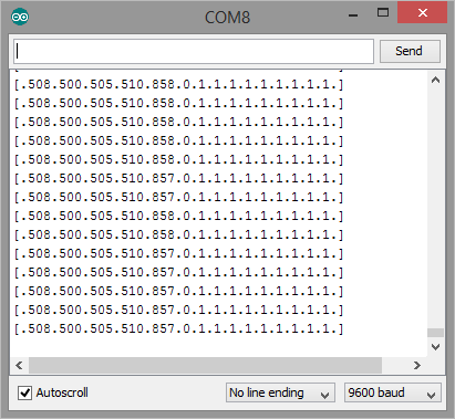 Sample debugging output
 - Write a scale() function that maps a number from 0-1023 to a value from -5 to 5. This -5 to 5 range will be used to represent direction and magnitude for all analog reads.
- Write a analogControl() function and add it in the loop() function. This function controls analog values and the mouse input based on Joystick input.
- Modify analogControl() to scale the mouse movement speed according to the left potentiometer. The scaling will modify the mouse movement speed by a factor between 2^-2.5 to 2^2.5 (inclusive).
- Modify the state array to also save the previous state in an array called pstate. This will allow the controller to detect when buttons are pressed, released, and held.
- Added functions wasPressed(), wasReleased(), and isHeld() for easily detecting button interaction.
- Write a buttonControl() function and add it in the loop() function. This function controls keystrokes when buttons are pressed and released.
- Added a global char array called bindings[] which maps buttons to their respective keystrokes. Modified buttonControl() to use this array.
- Added a turbo feature which changes button presses to no longer care if a button was pressed or released. If it is held, it will continuously mash button presses when held down.
Starting at step 8 in the previous list, I would run the program regularly to ensure all code was behaving as intended. Since I based everything off of bindings of a change in my global state array, I was able to examine that all keystrokes and button presses registered as I believed they would through the console before giving them any functionality.
Because of this, I never ran into any problems where the controller wildly misbehaved while coding (i.e. I never lost control of my mouse or had an infinite stream of some letter appearing on my screen).
I did test one feature I originally developed but removed due to its impracticality. Originally, I intended to use the right potentiometer to change the current keybindings. The idea was rather than having to recompile everytime you wanted to change what each button did, you could store 10 arrays and switch between them based on where the potentiometer was turned to. Unfortunately, the potentiometers I am using have a very small active range (a majority of their turning range is either max or minimum resistance) so this was challenging get it to the keybindings you wanted. I removed this feature because of this. The second potentiometer will be used to control the DS Touch Screens once those get incorporated into my controller.
Furthermore, I tested the controller once finished by playing some Team Fortress 2. I experimented with several keybindings and found that I preferred different setups for different classes. Thanks to my flexible design, I only need to change a few global variables at the top to reconfigure my keybindings.
Overall I am very happy with my controller. It meets all requirements and has two noteworthy extras. Additionally, I have begun experimenting with some new hardware that will be used in the second incarnation of this controller. My current experiments will be explained in the section below titled Hardware Experiments.
Requirements:
- Firmware that supports keyboard+mouse interaction
- left-stick -> 'wasd'
- right-stick -> mouse
- buttons -> click, space, etc.
Extras:
- Potentiometer for adjusting sensitivity
- Turbo switch
- Keybinding switch (removed since there wasn't suitable hardware at the moment)
Pictures:
I have learned a lot by writing this controller firmware. Between the coding and experimentation, I easily spent over about 6 hours worth of work on this. Additionally, I spent probably another 6 hours experimenting with my new parts, although I have not incorporated any of the parts onto the controller yet.
Looking forward to next week, I'm excited to see how my controller performs. That being said, I have a growing interest in designing a real plastic version of this controller and will start looking into that soon.
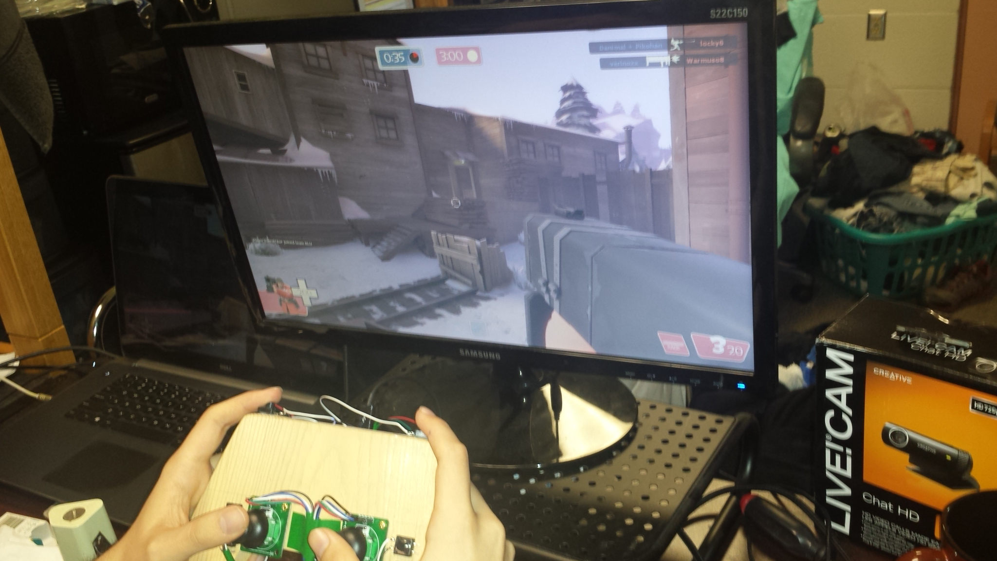 Playing TF2 with my completed firmware!
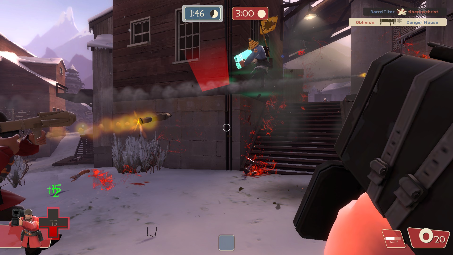 Getting a kill with my controller in TF2!
More pictures can be found here!
Over the course of this week, I received all the parts I was expecting in the mail. Additionally, I ordered a second Arduino Micro and got a Protoboard (similar to the ones used in HMC's Microprocessor class). Using the Nintendo DS screens is proving slightly challenging since there is a great amount of variance between individual DS screens. I am currently in the process of writing a calibration method, similar to those on the DS, to address this. I only just received the E-Ink screen and have not made any attempts to use this yet.
Also, I'm planning on looking into how to make a plastic mold for a high quality successor to this controller this week.
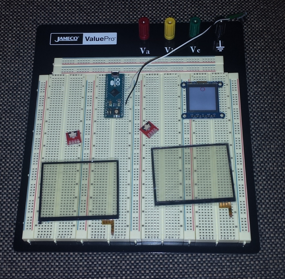 The hardware I am currently experimenting with for future inclusion with my controller.
The current firmware code is hosted in this repo. A link to it can be found here.
I will revise this code in the future once I incorporate my new hardware. Additionally, I may clean up a few things to make the code cleaner to follow and write more documentation, since it is currently pretty minimal.
