Skip to content
New issue

Have a question about this project? Sign up for a free GitHub account to open an issue and contact its maintainers and the community.

By clicking “Sign up for GitHub”, you agree to our terms of service and privacy statement. We’ll occasionally send you account related emails.

Already on GitHub? Sign in to your account

Sonoff Basic new Layout #4515

Closed
reloxx13 opened this issue Dec 3, 2018 · 69 comments
Closed

Sonoff Basic new Layout #4515

reloxx13 opened this issue Dec 3, 2018 · 69 comments
Labels
enhancement Type - Enhancement that will be worked on

Comments

@reloxx13
Copy link
Contributor

reloxx13 commented Dec 3, 2018

Heya,

the Sonoff Basics got a new Board Layout.

GPIO14 is gone and now there is a GPIO2 (IO2 and its not a borehole!).


Flashing process is the same

Disconnect all power, hold down push button while powering up usb - keep button down for 2 seconds and then flash as per wki... no difference.

Some picky devices want you to hold the button down during the entire process - not sure if you maybe have one of these.


In the Template GPIO2 is disabled, so dunno if u want to add a new Layout or allow GPIO2 for the Sonoff Basic.

Workaround: Use Generic Template and set GPIOs yourself.

Template:
https://github.com/arendst/Sonoff-Tasmota/blob/development/sonoff/sonoff_template.h#L520

https://forum.creationx.de/forum/index.php?thread/1254-sonoff-basic-neueste-version-gpio14/

https://forum.creationx.de/forum/index.php?thread/1254-sonoff-basic-neueste-version-gpio14/

@Jason2866
Copy link
Collaborator

Hello @reloxx13
is it a real ITEAD Sonoff Basic? For me the typical ITEAD sticker on relais is missing.
Maybe just a (good?) clone...

@andrethomas
Copy link
Contributor

andrethomas commented Dec 3, 2018

At least it seems they are addressing the thermal issue since this board appears to have 9 via's from the bottom of the ESP8266 chip coming through to the bottom onto what seems to be a much larger ground plane than in the older versions.

@andrethomas
Copy link
Contributor

@reloxx13 Is that a ESP8285 on there?

@reloxx13
Copy link
Contributor Author

reloxx13 commented Dec 3, 2018

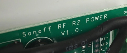
@andrethomas yep, you will find better pictures here: https://smarthome.schimmer-media.de/forum/index.php?thread/2370-neuer-sonoff-basic-oder-ganz-altes-modell/&postID=26177#post26177

@Jason2866 im pretty sure those are orginal itead's. there are also some other R2 versions with the esp8285. guess they are changing all their products to that chip. Sonoff Dual R2.

https://smarthome.schimmer-media.de/forum/index.php?thread/2370-neuer-sonoff-basic-oder-ganz-altes-modell/&postID=26177#post26177

Some more infos here (in german):
https://forum.creationx.de/forum/index.php?thread/1254-sonoff-basic-neueste-version-gpio14/

https://smarthome.schimmer-media.de/forum/index.php?thread/2370-neuer-sonoff-basic-oder-ganz-altes-modell/

@andrethomas
Copy link
Contributor

@reloxx13 @Jason2866

This is good news - so in future we will not have thermal issues with the new sonoff basic's I think.

@andrethomas
Copy link
Contributor

I think just adding GPIO2 to the Sonoff Basic template will not cause harm as GPIO2 is not used on the previous editions of the Sonoff Basic.

@andrethomas
Copy link
Contributor

Or it will be easier for user to select different version and template will dictate where POWER is.

@ascillato
Copy link
Contributor

I think that would be better and less confusing for people to just add gpio2 to the sonoff basic template

@ascillato
Copy link
Contributor

Lets make a PR and that Theo decides ;)

@andrethomas
Copy link
Contributor

Yeah, just adding GPIO2 is fine.

image

@arendst
Copy link
Owner

arendst commented Dec 3, 2018

Just add gpio2 please ;-)

@ascillato
Copy link
Contributor

ascillato commented Dec 3, 2018

@reloxx13 your call ;)

@ascillato2 ascillato2 added enhancement Type - Enhancement that will be worked on add to wiki labels Dec 3, 2018
@andrethomas
Copy link
Contributor

#4518

@ascillato2
Copy link
Collaborator

Closing as the PR has been made. Thanks everyone for sharing theirs ideas.

We also need to add this information to the wiki. I will do that later. Thanks.

@reloxx13
Copy link
Contributor Author

reloxx13 commented Dec 3, 2018

im too late :D

@reloxx13
Copy link
Contributor Author

reloxx13 commented Dec 3, 2018

i wrote sth in the wiki for that, feel free to edit/move it, im not sure where to place it on the basic page.

https://github.com/arendst/Sonoff-Tasmota/wiki/Sonoff-Basic#new-board-layout

Version needs to be added if its released.

@jimmyhall82
Copy link

How do I update the template used on my Tasmota sonoff? I flashed with most recent firmware but I don’t have gpio2 listed in the configuration template

@ascillato
Copy link
Contributor

Use latest Tasmota version 6.3.0.15 (http://thehackbox.org/tasmota/)

@reloxx13
Copy link
Contributor Author

reloxx13 commented Dec 5, 2018

(its not released now, its in the dev version, which ascillato linked)

@jimmyhall82
Copy link

@ascillato thanks

@joydeepsaha05
Copy link

@reloxx13 I have the same board and was trying to flash Tasmota, but it fails to get detected by my computer. Were you able to successfully flash it? Are the flashing steps different for the new board?

@andrethomas
Copy link
Contributor

@joydeepsaha05

Are the flashing steps different for the new board?

No, exactly the same.

@joydeepsaha05
Copy link

@andrethomas Thanks for confirming. I was able to flash using a Raspberry Pi, must've been something wrong with my FTDI adapter.

@hudecitydave
Copy link

THANKS for the work here!
Now I try to power up a SR505 PIR sensor on GPIO02/IO2.
Has anyone found a 5V pin to get the needed power on the new board?
Thanks for info!

@ascillato
Copy link
Contributor

The sonoff basic R2 does not have enough power to power another device. Sorry. The hardware was not designed for that.

@czarnikjak
Copy link

Any possibility to use RX or TX pins to connect DHT sensor?

@Jason2866
Copy link
Collaborator

Jason2866 commented Jan 13, 2019

Why not? connect it to RX Disable serial logging

@petersendk
Copy link

hi i also have new versions and i tried to add ic2 on rx and tx and want to look at a value of a ads1115. I look at the sonoff_sensors optionslist at github that it should support it, but after flashing everything ok. I can toogle relais from homeserver, green light blinks slowly. I can test gpios on webinterface it says :{"GPIO1":"5 (I2C SCL)","GPIO2":"0 (None)","GPIO3":"6 (I2C SDA)","GPIO4":"0 (None)","GPIO14":"0 (None)"}
but it does not show any other signs of ads1115 when i connect the board ??. Should it show ? or what am i doing wrong.
i tried sonoff_bin 523k | 20190113 and sonoff_sensors 554k | 20190113 from the hackbox. also tried normal sonoff_bin from github.

I tried flashing the espeasy ESP_Easy_mega-20190109_normal_ESP8285_1024.bin.
It works with the same connection and board and i can see the values of the ads1115 analog inputs.
But i like the tasmota better. ?? pls info or help.
do you need any other info? ,pls bear with me i´m a newbee.

@petersendk
Copy link

Hi forgot to write i tried 3,3v i tried 5,5v i tried adress 48, i tried adress 49 without luck. i also tried generic sonoff, but after configuring and at first boot it stopped.

@petersendk
Copy link

It seems that a scan for i2c sensors take about 5 minutes first time after pwr up, after this everything ok.

@cosmos1978
Copy link

Does gpio 3 (rx) have a buildin pullup resistor ?
I have a sonnof with long cables now on gpio 2 and since there is no pullup lots of ghost switching.

@andrethomas
Copy link
Contributor

@cosmos1978 Yes

@cbugeja
Copy link

cbugeja commented Jan 16, 2019

Apologies but I'm still very very new to all this...
I need to set up a Sonoff Basic with 2 external sensors (reed switches) to work independently from the relay. The cable from the sensors to the sonoff needs to be 10mtrs max.
I was thinking of using GPIO4 and GPIO14. Is this a good choice once the sensors are not momentary switches?
Would I need to attach any resistors to these to avoid what @cosmos1978 referred to as ghost switching?

@georgia088
Copy link

@ivanmarban

@eric-void @andrethomas any workaround ?

I use GPIO3 (RX) and GND connected to a wall switch and it works great.
Moreover, it doesn't require additional soldering as i already solder it to flash.

I am new to all this, so I am trying to understand. You are soldering wires from GPIO3 (RX) and GND to a standard Wall Switch (not momentary/rocker). Then setting GPIO3 to (GPIO3 Serial In - Switch1 (09)) in Tasmota?

Is this correct? Does it work as it should?

Thanks!!

@utech-git
Copy link

@ivanmarban @andrethomas Looking at tasmota documentation, it's not true that "it should work the same as GPIO14"
In https://github.com/arendst/Sonoff-Tasmota/wiki/Expanding-Sonoffs#restrictions, you can read "GPIO2 can’t be low at boot, so you can’t connect a switch to it".
If the documentation tells the truth, using GPIO2 as a switch could give some problems (if the device reboots for any reason and the switch is off the device will not boot normally).

I can confirm this. Just tried this morning. Connecting GPIO2 and Ground to a "standard" wall switch (not push button) first seems to work normally as it should. But if for some reason the device reboots and the switch is in the "low" position, it doesnt boot. You have to turn the device off, change the switch position, then turn it on again.

But as @ivanmarban said, i connected ground and GPIO3 (RX) and it seems to work correctly with the "standard" wall switch. No problemas at booting either.

Can someone confirm that using it like this (Ground and GPIO3/RX with a wall switch) has no problem at all?

Thanks for everybody in this thread. Really helped me understanding and setting up tasmota with this new board layout!!!! \o/

@utech-git
Copy link

@ivanmarban

@eric-void @andrethomas any workaround ?

I use GPIO3 (RX) and GND connected to a wall switch and it works great.
Moreover, it doesn't require additional soldering as i already solder it to flash.

I am new to all this, so I am trying to understand. You are soldering wires from GPIO3 (RX) and GND to a standard Wall Switch (not momentary/rocker). Then setting GPIO3 to (GPIO3 Serial In - Switch1 (09)) in Tasmota?

Is this correct? Does it work as it should?

Thanks!!

Yes, my friend. That's perfect. I just did it this morning and works like a charm.
As I said in my reply just above this one: i just want someone to confirm that this setting has no other problems. But i can confirm that is working so far :)

@georgia088
Copy link

@ivanmarban

@eric-void @andrethomas any workaround ?

I use GPIO3 (RX) and GND connected to a wall switch and it works great.
Moreover, it doesn't require additional soldering as i already solder it to flash.

I am new to all this, so I am trying to understand. You are soldering wires from GPIO3 (RX) and GND to a standard Wall Switch (not momentary/rocker). Then setting GPIO3 to (GPIO3 Serial In - Switch1 (09)) in Tasmota?
Is this correct? Does it work as it should?
Thanks!!

Yes, my friend. That's perfect. I just did it this morning and works like a charm.
As I said in my reply just above this one: i just want someone to confirm that this setting has no other problems. But i can confirm that is working so far :)

Awesome! Do you have to install a pull up resistor, or does it work with a built in one?
P.S. I posted this same basic question as a new issue because this thread shows "closed". I wasn't sure if it would get viewed. I apologize!

@utech-git
Copy link

@ivanmarban

@eric-void @andrethomas any workaround ?

I use GPIO3 (RX) and GND connected to a wall switch and it works great.
Moreover, it doesn't require additional soldering as i already solder it to flash.

I am new to all this, so I am trying to understand. You are soldering wires from GPIO3 (RX) and GND to a standard Wall Switch (not momentary/rocker). Then setting GPIO3 to (GPIO3 Serial In - Switch1 (09)) in Tasmota?
Is this correct? Does it work as it should?
Thanks!!

Yes, my friend. That's perfect. I just did it this morning and works like a charm.
As I said in my reply just above this one: i just want someone to confirm that this setting has no other problems. But i can confirm that is working so far :)

Awesome! Do you have to install a pull up resistor, or does it work with a built in one?
P.S. I posted this same basic question as a new issue because this thread shows "closed". I wasn't sure if it would get viewed. I apologize!

No, I didn't install any pull up resistor. It hasn't exploded nor set my house on fire yet, so far so good :)

But a few posts above AndreThomas said it has a buildin pull resistor already.

@2016for
Copy link

2016for commented Jan 25, 2019

@ivanmarban

@eric-void @andrethomas any workaround ?

I use GPIO3 (RX) and GND connected to a wall switch and it works great.
Moreover, it doesn't require additional soldering as i already solder it to flash.

Can I use this + use GPIO1/TX, 3.3, & GND for PIR sensor?

@2016for
Copy link

2016for commented Jan 25, 2019

The sonoff basic R2 does not have enough power to power another device. Sorry. The hardware was not designed for that.

Just a small update to that: I managed to solder a small cable to GPIO2/IO2, and ordered some HC-SR501 PIR Sensors. Bringing them to power with 3,3V works as charme. (like this: https://randomnerdtutorials.com/modifying-cheap-pir-motion-sensor-to-work-at-3-3v/)

Now we have the next room hassio enabeld :-)

Installing PIR on GPIO2 isn't causing any problems like should be low on boot or something?
Someone suggested me to use GPIO1/TX for PIR, would that be ok/better/same as your GPIO2 connection?

@andrethomas
Copy link
Contributor

@h4nc usually when devices are used for purposes other than the original intention bad things happen. The problem with posting it here is that it gives other people bad ideas so I'll be removing it shortly.

Repository owner deleted a comment from h4nc Jan 25, 2019
Repository owner deleted a comment from meingraham Jan 25, 2019
Repository owner deleted a comment from h4nc Jan 25, 2019
Repository owner deleted a comment from meingraham Jan 25, 2019
Repository owner deleted a comment from andrethomas Jan 25, 2019
Repository owner deleted a comment from h4nc Jan 25, 2019
@h4nc

This comment has been minimized.

@georgia088

This comment has been minimized.

@andrethomas

This comment has been minimized.

@h4nc

This comment has been minimized.

@andrethomas

This comment has been minimized.

@h4nc

This comment has been minimized.

Repository owner locked as off-topic and limited conversation to collaborators Jan 26, 2019
Sign up for free to subscribe to this conversation on GitHub. Already have an account? Sign in.
Labels
enhancement Type - Enhancement that will be worked on
Projects
None yet
Development

No branches or pull requests