/
sonoff_IW100
33 lines (27 loc) · 2.43 KB
/
sonoff_IW100
1
2
3
4
5
6
7
8
9
10
11
12
13
14
15
16
17
18
19
20
21
22
23
24
25
26
27
28
29
30
31
32
33
---
date_added: 2020-02-14
title: Sonoff IW100
model: IW100TPB
category: plug
type: Wall Outlet
standard: us
flash: serial
image: https://user-images.githubusercontent.com/5904370/73012669-16729780-3e17-11ea-8b4c-c0ace8c9811c.png
template: '{"NAME":"Sonoff IW100","GPIO":[17,145,0,146,0,0,0,0,21,157,0,0,0],"FLAG":0,"BASE":41}'
mlink: https://sonoff.tech/product/wifi-smart-wall-swithes/iw100-101
link: https://itead.cc/product/sonoff-iw100-iw101/
link2: https://www.aliexpress.com/item/1005001846133175.html
link4: https://www.amazon.com/IW100-Monitoring-Compatible-Neutral-Required/dp/B081JMG1WN
link3: https://www.banggood.com/SONOFF-IW100IW101-US-WiFi-Smart-Power-Monitoring-Wall-Socket-Switch-Work-with-Amazon-Alexa-and-Google-Assistant-Voice-Control-LAN-Control-p-1593946.html
---
<div style="float:right; margin:10px; text-align: center;"><img style="width:50px" src="/assets/device_images/blakapproved.webp"> <br><b> by <a href="https://blakadder.com">blakadder</a></b></div>
Another great new design by Sonoff! Plug with power monitoring and an additional button that can control the outlet or be configured in Tasmota to control anything else. The plug uses a Chipsea CS7598 for power monitoring (similiarly to the trusty [S31](sonoff_S31)). The relay is rated to 15A 125V or 10A 250VAC. It is even working with 230V with a small load (LED bulb).

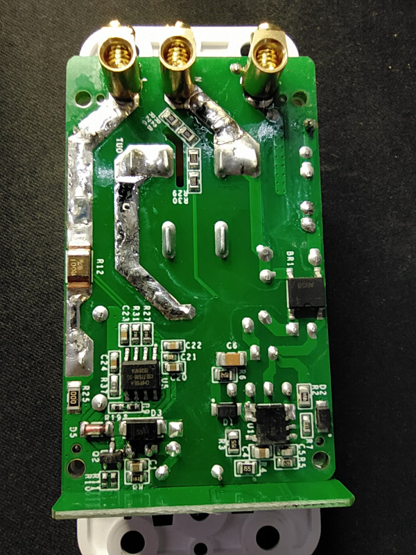
The switchplate is removable and is held on only by a few plastic clips. Access to the internals requires unscrewing 4 screws. After removing them we see the main PCB with mains electricty, a wifi daughterboard soldered on to it and the touch pad board connected with a 6 pin header.

## Serial Flashing
Necessary GPIO's are neatly broken out on bottom left, albeit only on pads. To put the device into flash mode you need to ground GPIO0 using a wire to connect the two during boot (I recommend using a dupont wire on the header that connects to the switchplate). See image for pin locations.

Follow the standard flashing procedure and that's it.
