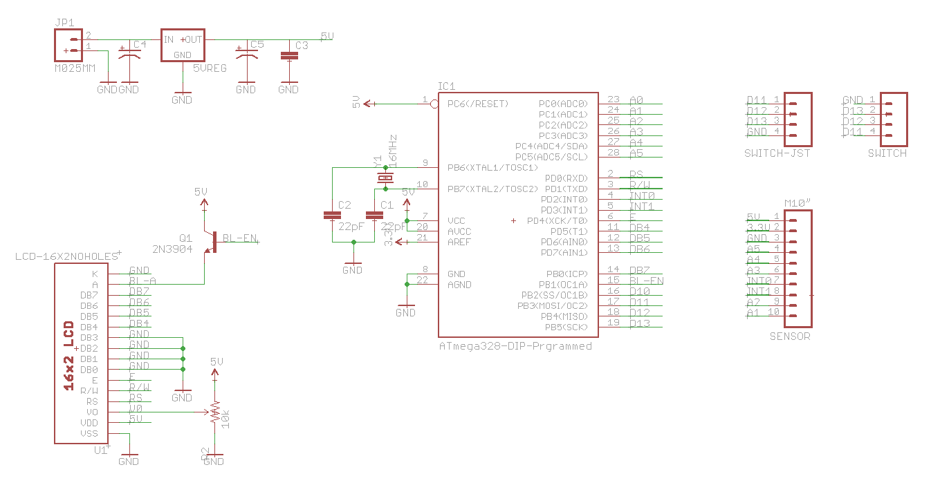
Here is the Eagle schematic and board layout for the CTAIM1. Software can be found here: https://github.com/camerontech/offroad-cpu
If picking up and assembling all of these parts yourself is a bit daunting, you can purchase a kit or pre-assembled unit here: http://store.camerontech.io/products/offroad-cpu
1 x ATMEGA328P-PU ATMEGA 328
1 x LCD SparkFun LCD-00709
1 x Multi-sensor 10DOF Board
1 x 5v Regulator Digikey MC7805CT-BPMS-ND
1 x 16MHz Clock Crystal Mouser 815-ABL-16-B2
1 x 10kΩ Potentiometer Digikey D4AA14-ND
2 x 10µF Capacitor Digikey P975-ND
1 x 0.1F Capacitor Digikey 399-4266-ND
2 x 22pF Capacitor Digikey 399-9723-ND
1 x NPN Transistor Mouser 512-2N3904BU
1 x 40-pin Straight Header SparkFun PRT-00116
1 x 40-pin Right-angle Header SparkFun PRT-00553
1 x Three-way switch Three-way Rocker Switch
1 x Three-way switch breakout board Breakout Board
That'll get you everything you need to get it working. You'll still need to connect the three-way switch to the board somehow and get power in.
A 4-wire JST connector hooks up the three-way switch to the circuit and also lets you disconnect it:
1 x 4-pin JST Connector SparkFun PRT-09916
You can solder 12v right to your circuit, or use a 9v battery. If you want something less permanent then use a screw terminal so you can unhook the wires again if necessary:
1 x 2-pin screw terminal SparkFun PRT-08432
1 x 9v Battery Strap Digikey 81-8K-ND
Finally, unless you want to do a lot of wire-routing and excess soldering by hand and manually following the schematic to hook everything up, you can also get the circuit board that lays everything out nicely and attaches as a backpack to the LCD screen:
1 x Offroad CPU Circuit Board Cameron Tech CTORD100