add multi port transformer #618
Comments
|
Hmmm. There are zillions of possible combinations. I would go the subcircuit way in this case, or just drawing it with inductances. |
|
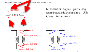
To ease the drawing of such things, what probably can be done is to add anchors to normal L that are at the same positions as transformers' "dot" anchors are...
...what do you think? |
|
This could be very useful. If you can find a solution for the positioning of the "core" (the two parallel lines) between two inductors the problem would be solved. |
This is easily done with plain TikZ: \documentclass{article}
\usepackage[T1]{fontenc}
\usepackage{graphicx}
\usepackage{circuitikz}
\begin{document}
\begin{tikzpicture}
\draw (0,3) -- ++(1,0) to[L, name=L1] ++(0,-2) -- ++(-1,0);
\draw (0,0) -- ++(1,0) to[L, name=L2] ++(0,-2) -- ++(-1,0);
\draw (3,1.5) -- ++(-1,0) to[L, name=L3] ++(0,-2) -- ++(1,0);
\coordinate (x at center) at ($(L1.center)!0.5!(L3.center)$); % we will use just the x part
\draw [thick, double,double distance=4pt] (x at center|-L1.left) -- (x at center|-L2.right);
\end{tikzpicture}
\end{document}
|

|
...and really, also the whole thing is not-so-difficult... \documentclass{article}
\usepackage[T1]{fontenc}
\usepackage{graphicx}
\usepackage{circuitikz}
\begin{document}
\begin{tikzpicture}
\draw (0,3) -- ++(1,0) to[L, name=L1] ++(0,-2) -- ++(-1,0);
\draw (0,0) -- ++(1,0) to[L, name=L2] ++(0,-2) -- ++(-1,0);
\draw (3,1.5) -- ++(-1,0) to[L, name=L3] ++(0,-2) -- ++(1,0);
\coordinate (x at center) at ($(L1.center)!0.5!(L3.center)$); % we will use just the x part
\draw [thick, double,double distance=4pt] ([yshift=1cm]x at center|-L1.left) -- ([yshift=-1cm]x at center|-L2.right);
\draw (L1.left) ++(-0.3,0) node[circ]{};
\draw (L2.right) ++(-0.3,0) node[circ]{};
\draw (L3.left) ++(0.3,0) node[circ]{};
\end{tikzpicture}
\end{document}
|

|
I think that this is the best solution for my problem.. |
|
Will be in the next release the extra anchors in the inductor? |
Yes --- see the linked PR #625 |
It could be very useful the introduction of multiport transformer, where we have one (o more) primary winding e two (o more) secondary winding (even 1 primary and 2 secondary will be very useful).
example:
https://www.electronics-tutorials.ws/wp-content/uploads/2018/05/transformer-trans59.gif
Thanks.
The text was updated successfully, but these errors were encountered: