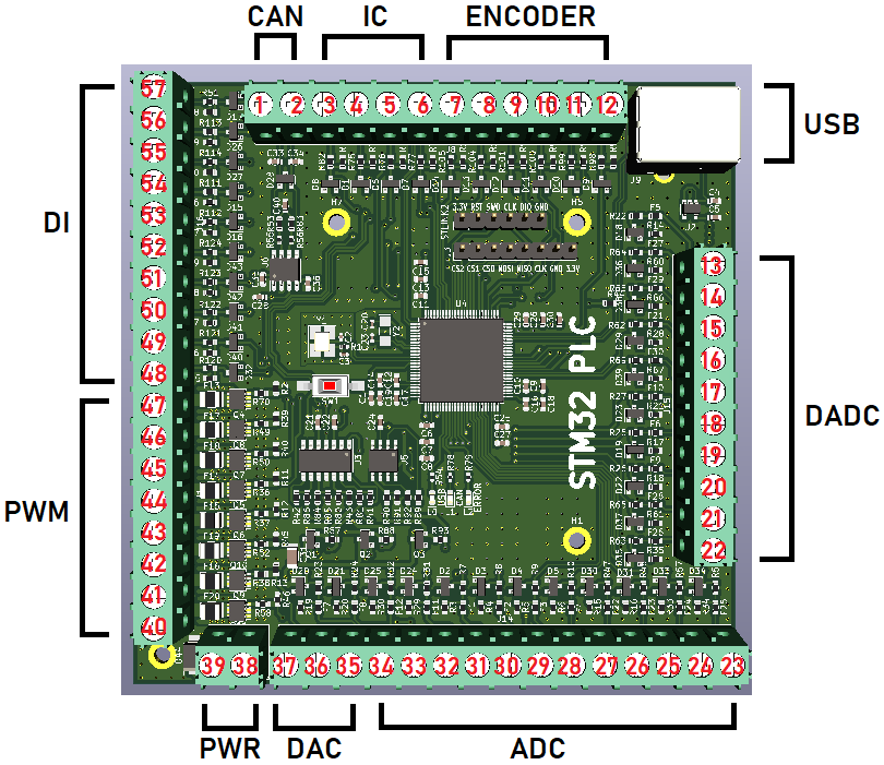
This project is a PCB bord that has the following measurement and control input/output:
- 12 x ADC at 16-bit resolution for 0-20mA input with programmable gain
- 5 x Differential ADC at 16-bit for 0-20mA input with programmable gain
- 3 x DAC at 12-bit with 0-20mA output
- 8 x PWM for 0-2.2A with N-channel MOSFET
- 10 x Digital Input
- 1 x CAN-bus channel
- 4 x Input Capture for 0 kHz to 10kHz
- 3 x Encoder for -32768 to 32767 pulses
- 1 x USB port for connecting with OpenSourceLogger and GoobySoft
- 1 x SPI with 3 chip select for ILI9341 LCD with touch
- 1 x ST-Link V2 connection
- 1 x RTC clock with two alarms A(date) and B(week day) and a battery holder so the RTC remembers the date and time
- All ADC, Digital Input, Differential ADC, Input Capture and Encoder are high voltage protected with PTC(fall current 30mA) fuse + 3.6v zener diode.
- All PWM and DAC are high voltage protected with N-channel MOSFET and PNP-transistor and OP-amp.
- The CAN-bus channel is high voltage peak protected for 3000V under a short time with a TVS-diode. The CAN-bus transmitter itself can hold against -14V to +14V, but the TVS-diode has a limit around 6V.
The documentation for the pin map can be found in the Documentation folder. Also all the article numbers for each component can be found in at the DAC ADC PWM IO.sch file in the PCB folder. Just double click on a PCB symbol and see the Mouser Electronics article number of the electrical component.
Yes, it's possible to set the calibration to each input in this project. You need to have the ILI9341 touch LCD with SPI bus. Open the STM32 PLC Pinouts.pdf and see the connection for the LCD. You can also set the PWM frequency and analog input gain for the ADC and Differential ADC at 16-bit.
The STM32 PLC has internal SAE J1939 protocol. Made from Open-SAE-J1939 repository.
This is a QT C++ software that you can connect to your STM32 PLC board via the USB and then you can send signals from OpenSourceLogger and recieve signals. OpenSourceLogger is a very easy to use logging and controlling software and it stores data at a SQL server.
This is a ImGui C++ project that do the same as OpenSourceLogger, but it's much better and have more features. The reason why I moved away from QT C++ to ImGui C++ is because it's much easier to write a GUI application in C++ by using ImGui instead of QT. With QT, you are stuck with object oriented programming. Everything is a class. But for ImGui, you can choose which type of lever you want to code, I prefer C-style C++ code with a small dose of object oriented programming (if needed).
Consider that I will work on GoobySoft instead of OpenSourceLogger.
The STM32 PLC has a lot of functions you can select by touching the LCD.
- A:Show measurement and time
- B:Set analog gain
- C:Set PWM frequencies
- D:Set analog input calibration
- E:Set pulses per encoder revolution
- F:Set date and time and alarm
- G:Do a PGN request
- H:Show ECU addresses
- I:Commanded address
- J:Show this ECU DM1 codes
- K:Show other ECU DM1 codes
- L:Show this ECU DM2 codes
- M:Show other ECU DM2 codes
- N:Show this ECU name
- O:Show other ECU name
- P:Show this ECU identifications
- Q:Show other ECU identifications
- R:SAE J1939 Auxiliary valve command
- S:Analog in to PWM
- T:Analog in to analog out
- U:About STM32 PLC
- Download this repository
- Download & Install KiCad
- Open the
PCBfolder and open the.profile with KiCAD and greate agerberfile of your own choice - Go to your PCB manufacturer and give them the
gerberfile and let them produce the board for you - Order the eletrical components from
Mouser Electronics - Once you have the eletrical components and your PCB board, it's time to solder them.
- Once the PCB board is finished, then install STM32CubeIDE
- Open the
Codeproject and import the.iocproject file using STM32CubeIDE - Flash the board with the
Ccode by using ST-Link V2 connection - Connect the ILI9431 touch LCD and then you are done!
- KiCAD: 6.0.7
- STM32CubeIDE 1.10.1
It's done. I don't plan to update this project. Everything is working and it will remain that way.