![]()
- Overview
- Getting started
- SSL support
- Local services
- Wireless configuring
- Pin definition
- Auxiliary
- GPIO
- ADC
- PWM
- UART
- I2C
- SPI
- Onewire
- Devices
- devices/ds18b20/read
- devices/lm75/read
- devices/dht11/read
- devices/dht22/read
- devices/si7021/read
- devices/bmp180/read
- devices/bmp280/read
- devices/bh1750/read
- devices/mpu6050/read
- devices/hmc5883l/read
- devices/pcf8574/read
- devices/pcf8574/write
- devices/pcf8574/hd44780/write
- devices/mhz19/read
- devices/mcp4725/write
- devices/pcf8591/read
- devices/pcf8591/write
- devices/ads1115/read
- devices/ina219/read
- devices/mfrc522/read
- devices/mfrc522/mifare/read
- devices/mfrc522/mifare/write
- devices/pca9685/control
- devices/mlx90614/read
- devices/max6675/read
- devices/max31855/read
- devices/tm1637/write
- License
This document explains the set of REST API commands to control your remote ESP8266 — an incredible all around IoT chip. For more information about ESP8266 please refer to wiki.
Once ESP8266 device is connected you can issue commands using DeviceHive's RESTful API or local REST API hosted right on the chip. It can be a JavaScript, python or anything that supports HTTP and JSON, even command-line curl.
Example using curl on Mac or Linux:
curl -H 'Authorization: Bearer eiMfp26Z+yRhiAafXWHCXT0LofwehgikmtygI6XoXIE=' \
-H 'Content-Type: application/json' \
-d '{"command":"gpio/write","parameters":{"1":0}}' \
http://nn8571.pg.devicehive.com/api/device/astaff/command
This would set pin GPIO1 to 0. For example on Adafruit's Huzzah ESP8266 modules
with PIN1 connected to LED it will turn the LED on.
In the same way local RESTful API can be used. Just run:
curl -H 'Authorization: Bearer eiMfp26Z+yRhiAafXWHCXT0LofwehgikmtygI6XoXIE=' \
http://eps-device-id.local/api/gpio/read
This command prints input state of all GPIO pins with json format.
The same idea with other interfaces. To check if your hardware device is suitable with firmware check which interface your devices has and then check if this interface is supported by DeviceHive ESP8266 firmware.
The latest version can be found in git project repository. There are sources codes and binary images.
The purpose of this firmware is to provide easy tool for building IoT solutions for developers which used to program on unsuitable for microcontroller programming languages. You can easily use AngularJS framework for example to implement your idea. Also, considering chip price, DeviceHive usability and plenty modules on market which are not require soldering, it looks like perfect tool for prototyping. DIY developers also may find this firmware very useful for their project.
First of all firmware has to be flashed into chip memory and chip has to be configured to use specified Wi-Fi network and DeviceHive server (can be omitted for local usage). Board should have at least 512KiB of ROM memory. Developers can build firmware and all tools for flashing and configuring by himself from sources. Or it can be downloaded from git repository: go to releases page and download archive with the latest version.
Before flashing chip needs to be connected to computer via USB-UART converter, CH_PD pin have to be connected to Vcc, GPIO15 and GPIO0 have to be connected to ground and 3.3V power supply should be used. Sample for most popular pre soldered modules connection is below:


Real connection sample:

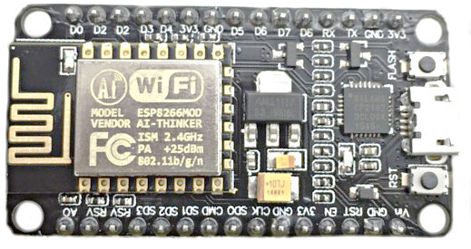
Also, it's possible to use NodeMCU boards. It already has UART converter, reset and flash buttons on board. So there is no need to assemble anything. Such module looks like:
After assembling, connect it to computer. Install driver for your USB->UART converter. The most popular chip and official sites with drivers below:
Make sure that virtual serial port is available in your system (virtual COM is present on Windows OS, /dev/ttyUSB* on Linux, /dev/tty.* on OS X). Unpack archive with firmware and flash it running esp-flasher in terminal. Flasher automatically detects serial port and use devicehive.bin file for flashing. Successful flasher output is below:

Now remove wire from GPIO0 (leave it float or connect to high), reboot device and connect to firmware with esp-terminal util. You can also use any other tool that can connect to terminal via UART and support escape sequences, PuTTY or GNU screen for example. Port parameters are: 115200 8N1.
Notice: you can avoid configuring firmware with terminal and use wireless configuring procedure described in wireless configuring section instead. Wireless configuring procedure also can be used for end-user devices with this firmware.
Firmware terminal is a UNIX like terminal with few commands. It is used for configuring and debugging the chip. To see debug output type dmesg. To configure run configure command. Follow instructions in terminal. You need to know DeviceHive server credentials to work with cloud services.
For the very beginning or DIY purpose you can use DeviceHive free playground located here Register there and you will have your own DeviceHive server instance. DeviceHive server can be deployed in local network or on some cloud hosting services. Follow for DeviceHive server deployment instructions on http://devicehive.com.
Configuring sample is below:

If DeviceHive API URL isn't specified, chip will work only as local RESTful server. Key is used for local RESTful API and remote DeviceHive server. For the current server implementation, key can be JWT AccessToken or RefreshToken. In second case, it will be automatically exachanged to AccessKey on each restart or expiration. See Local RESTful API for details about key usage with RESTful API.
After rebooting you can send commands to DeviceHive server or local RESTful API and ESP8266 perform them. List of accepted command is in this document. You can use DeviceHive web admin control panel to send command for test purpose or learning. Go to web admin, Devices tab, Commands sub-tab, Enter new command. Type command and parameters and press Push. After ESP8266 perform your command you can press Refresh button to see a result. For example gpio/read command would look in admin control panel as below:

Now you can start writing your own program to create your own IoT devices with your favorite language and frameworks using DeviceHive RESTful API which you can transmitted with HTTP(S) or Websockets. List of accepted command for ESP8266 is listed in this document.
Firmware supports encrypted WebSocket server connectity using Transport Layer Security (TLS). Server should support TLSv1.1 and TLS_RSA_WITH_AES_128_CBC_SHA or TLS_RSA_WITH_AES_256_CBC_SHA cipher.
Please note, chip has 2 KB buffer for secure data, so ssl handshake should not be more otherwise connection reset would occur. To check size of the handshake, run this command:
openssl s_client -connect devicehive.com:443 -tls1
and check in the output line with handshake size:
SSL handshake has read 4796 bytes and written 336 bytes
Firmware sets chip hostname and announce chip with mDNS using configured DeviceId. Hostname is limited with 32 chars, further DeiviceId's chars are omitted.
mDNS(multicast Domain Name System) can resolve local domain names to IP address. Firmware announce itself in mDNS using DeiviceId. mDNS 2nd level domain is limited with 60 chars, so any subsequent chars of DeviceId are omitted. Top level domain is always .local. mDNS-SD (service discovery) is supported. Service name is _esp8266-devicehive._tcp.local. This service points to local web server with RESTful API. One TXT record with firmware version is present.
A RESTful API is an application program interface (API) which uses HTTP requests for calling remote procedures. In this implementation such procedures is commands for chip. There is a tiny web server on chip port 80 which provides local RESTful API. API endpoint is http://device-id-or-ip.local/api/. Firmware commands are available as sub paths of API endpoint. For example command api/master/read available at http://device-id-or-ip.local/api/spi/master/read. Any parameters should be passed as json in request body. On success, request will be responded with 2xx HTTP code and 4xx on error. Commands, its parameters and return values are the same as for DeviceHive cloud server except notifications. Any notifications are not supported, so commands for subscribing on it also don't available. GET and POST method are supported, and there is no difference for API, but GET should be sent with a content in a single TCP packet and POST supports only one simultaneous connection. HTTP access control allows any request origin. If device has Key, endpoint require authentication with HTTP header Authorization: Bearer YourKeyHere.
For example, we would like to set up pin GPIO1 to high state and chip has Key configured. curl request is:
curl -i -H 'Authorization: Bearer SomeKeyHere' \
http://eps-device-id.local/api/gpio/write -d '{"1":1}'
Chip answers on this request 204 No content which means that operation successfully completed.
Firmware includes local HTTP server with tools for playing with API and some samples for some sensors. Web server available at chip's 80 port. Having DeviceId configured and mDNS compatible OS, it is possible to open web page at http://your-device-id-or-chip-ip.local/ in browser. To play with RESTful API there is a simple page http://your-device-id-or-chip-ip.local/tryapi.html where any command can be tried and command's output can be observed.
The original main page can be replaced with any other up to 65536 bytes. Only main page can be replaced, there is no way to add more pages. There is a tiny text editor at http://device-id-or-ip.local/editor.html which allows to edit page content in web browser and download/upload file. If page was changed, original page is always available at http://device-id-or-ip.local/help.html. Do not edit web page simultaneously from different tabs/browsers/computers.
This feature can be used to create web enabled IoT devices. Any HTML, CSS, JS or anything else can be saved there. Local web server provides this page as is, without any modifications. Embedded JS in web browser can be used for communicating with RESTful API. As an example, it's possible to build some sensor with web interface. A couple of such samples can found on the local web server. http://device-id-or-ip.local/help.html page contains a list of them.
Firmware can be configured to use chip as WiFi access point during configuration procedure. In this mode chip creates specified wireless network with WPA/WPA2 security protocol and server connectivy is disabled. In this mode all local services like mDNS, RESTful API, uploadable web page are available. This mode can be use to create local autonomous devices with a web interface.
Since DeviceHive ESP8266 firmware flashed into chip, it can be configured without any special devices or software. So this mode can be used in end-user projects to provide easy way of device configuration. If chip doesn't contain config, wireless configure starts automatically on boot. To enter configuration mode manually just reset device three times with chip RESET pin or button (if it is present on board). Intervals between resets should be more than half seconds and less than 3 seconds, i.e. simply reset device three times leisurely. If board has LED connected to TX pin, it turns on. ESP8266 will operate as Wi-Fi access point providing open wireless network with SSID 'DeviceHive'. Connect to this network with your laptop/phone/tablet or other device with Wi-Fi support. Device with iOS and OS X automatically will show configuration page like below:

Android devices will show notification 'Sign into Wi-Fi network' in bar:

Tap on it to open the same configuration page. In case of using other devices, just open browser and type URL: http://devicehive.config.
Also you can type any URL with http scheme in it, you will be redirected on URL above anyway while you are connected to ESP8266 in configuration mode.
Type your configuration in form and click Apply button. Device will be rebooted in 10 seconds in normal mode with new configuration.
Notice: You can automate configuration process for your devices. Actually to configure firmware you need to send HTTP POST request like below to 192.168.2.1:80
POST / HTTP/1.0
Host: devicehive.config
Content-Type: application/x-www-form-urlencoded
Content-Length: 80

ssid=ssid&pass=pass&url=http%3A%2F%2Fexample.com%2Fapi&id=deviceid&key=key
| Pin name in commands | Function | ESP8266 pin number | NodeMCU board pin |
|---|---|---|---|
| GPIO | |||
| "0" | GPIO0 | 15 | D3 |
| "1" | GPIO1, UART_TX | 26 | D10 |
| "2" | GPIO2 | 14 | D4 |
| "3" | GPIO3, UART_RX | 25 | D9 |
| "4" | GPIO4 | 16 | D2 |
| "5" | GPIO5 | 24 | D1 |
| "12" | GPIO12, SPI_MISO | 10 | D6 |
| "13" | GPIO13, SPI_MOSI | 12 | D7 |
| "14" | GPIO14, SPI_CLK | 9 | D5 |
| "15" | GPIO15 | 13 | D8 |
| ADC | |||
| "0" | ADC0 | 6 | A0 |
| Common | |||
| "all" | all pins in current group |
Note: GPIO6-GPIO11 usually connected to on-module EEPROM, that is why no API for this pins.
This is auxiliary command that is used to get a list of supported commands. This command has no parameters and output looks like:
{
 "commands":
 [
  "gpio/write",
  "gpio/read",
  "gpio/int",
  "adc/read",
  "adc/int",
  "pwm/control",
  "uart/write",
  "uart/read",
  "uart/int",
  "uart/terminal",
  ...
 ]
}
The command/list command is used on the tryapi.html page to provide command suggestion.
Each ESP8266 pin can be loaded up to 12 mA. Pins also have overvoltage and reverse current protection.
Sets gpio pins according to parameters specified. Pins will be automatically initialized as output when command is received. All pins will be set up simultaneously. Unlisted pins will remain unaffected.
Parameters:
JSON with a set of key-value pairs, where key is pin number and value "0" for LOW, "1" for HIGH or "x" for NOP, leaving pin unaffected. Sample below sets GPIO10 to LOW and GPIO11 to HIGH:
{
	"10":"0",
	"11":"1",
	"12":"x"
}
Returns "OK" on success or "Error" with description in result.
Reads the state of all GPIO pins. Only pins specified in the request will be initialized as input.
Parameters: JSON with a set of key-value pairs, where key is pin number and value is one of the following:
- "init" - in ESP8266 all pins are initialized as input by default. If pin was used as output in gpio/write or to interface with other peripherals before, pass this argument to re-init the pin before reading. Pullup state will not be affected.
- "pullup" - init pin as input and enable pullup
- "nopull" - init pin as input and disable pullup
Example:
{
	"10":"init",
	"11":"pullup",
	"12":"nopull"
}
Note: pull up and pull down are the SoC feature that allows to set input to high or low through resistor with very high resistance. By default each pin is not connected (Z) and reading will return random value. Enabling pull up feature puts a very weak high level on input pin by default and pull down sets very weak low level, thus making its state determined as 1 or 0.
Returns "OK" on success with result or "Error" with description in result.
Example:
{
	"0":0,
	"1":1,
	"2":0
}Allows you to subscribe to notifications (interrupts) on pin state change.
Parameters: JSON with a set of key-value pairs. Where key is pin number and value is one of the following:
- "disable" - disable notifications
- "rising" - send notification on rising edge
- "falling" - send notification on falling edge
- "both" - send notification on rising and falling edge
- "timeout" - notification will be sent only after a certain period of time. Minimum is 50 ms. Maximum is 8388607 ms. If not specified, previous timeout will be used. Default is 250 ms.
Mnemonic "all" can be used to set value for all pins.
Note: Timeout feature shall be used whenever is practical to avoid flooding with notifications.

Example:
{
	"all":"disable",
	"11":"rising",
	"12":"falling",
	"13":"both",
	"timeout":"100"
}
Returns "OK" on success with result or "Error" with description in result.
Notifications will be generated with the name "gpio/int". Each notification will contain list of gpio pins affected in "caused" field (read: pins that caused an interrupt), "state" contains values of all gpio inputs after timeout and "tick" contains the number of ticks of SoC's internal clock as a timestamp:
{
	"caused":["0", "1"],
	"state":{
		"0":0,
		"1":1,
		"16":0
	},
	"tick":123456
}ESP8266 has just one ADC channel. This channel is connected to a dedicated pin 6 - TOUT. ADC can measure voltage in range from 0.0V to 1.0V with 10 bit resolution.
Reads ADC channels values. ESP8266 has just one channel - "0".
Parameters: Can be empty, all channels will be sent in this case. JSON with a set of key-value pairs, where key is pin number and value is one of the following:
- "read" - read channel current value
Example:
{
	"0":"read"
}
Returns "OK" on success with result or "Error" with description in result. Each entry contains channel number and value in volts.
{
	"0":0.6
}Subscribes on notifications with ADC value with some period.
Parameters: Json with set of key-value, where key is ADC channel and value is period in milliseconds or "disable" for disabling. "0" value also means disable. Period can be from 250 till 8388607 ms.
Example:
{
	"0":"1000"
}
In this example value of channel 0 will be sent every 1 second. Return "OK" in status. Or "Error" and description in result on error. Notification will have name "adc/int" and following format:
{
	"0":"0.0566"
}
Where "0" channel number, and "0.0566" current voltage in volts.
ESP8266 has only software implementation of PWM which means there is no real-time guarantee on high frequency of PWM. PWM has just one channel, but this channel can control all GPIO outputs with different duty cycle. It also means that all outputs are synchronized and work with the same frequency. PWM depth is 100. PWM can be used as pulse generator with specified number of pulses.
Enable or disable PWM.
Parameters:
Json with set of key-value, where key is pin name and value is duty cycle. Duty cycle is an integer between 0..100, i.e. percent. Mnemonic pin "all" also can be used to control all GPIO pins simultaneously. To disable PWM for one of the outputs, just set value to "disable" or "0". PWM can be also disabled for pin if command "gpio/write" or "gpio/read"(only with some pins for initialize) is called for pin.
There are also additional parameters:
- "frequency" - set PWM base frequency, if this parameter was omitted, previous frequency will be used. ‘frequency" also can be set while PWM working or before command with pins duty cycles. Default frequency is 1 kHz. Minimum frequency is 0.0005 Hz, maximum is 2000 Hz
- "count" - the number of pulses that PWM will generate after command, maximum is 4294967295, 0 means never stop. Pins with 100% duty cycle will be switched to low level when PWM stops. Example:
{
	"0":"50",
	"frequency":"1000",
	"count":"10000"
}
This example starts PWM with square pulses for 10 seconds, duty cycle is 50%, frequency 1 kHz.
Return "OK" in status. Or "Error" and description in result on error.
Notes: PWM is can be used to generate single or multiple pulses with specific length: { "0":"100", "frequency":"1000", "count":"100"} - generate single pulse 100 milliseconds length { "0":"30", "frequency":"0.1", "count":"4"} - generate 4 pulses 3 seconds length, 7 seconds interval between pulses.
ESP8266 has one UART interface. RX pin is 25 (GPIO3), TX pin is 26 (GPIO1).
Read data from UART interface. Receiving buffer resets on each read or write command and may contain up to 264 bytes.
Parameters:
- "mode" - UART speed which can be in range 300..230400. After speed may contains space and UART framing parameters: number of bits(5-8), parity mode(none - "N", odd - "O" or even - "E"), stop bits(one - "1", two - "2"). Framing can be omitted,
8N1will be used in this case. If this parameter specified UART will be reinit with specified mode. If this parameter is omitted, port will use current settings (115200 8N1by default) and will not reinit port. - "data" - data string encoded with base64 which would be sent before reading. Reading buffer will be cleared and will contain data which is received during "timeout" time only otherwise data will be since last read, write command or since last notification sent. Data size have to be equal or less than 264 bytes.
- "timeout" - Can be used only with "data" field. Delay in ms for collecting answer after transmitting data. Maximum 1000ms, if not specified 250 ms is used.
Example:
{
	"mode":"115200",
	"data":"SGVsbG8sIHdvcmxkIQ=="
}
Return "OK" in status and json like below in result on success. Or "Error" and description in result on error.
{
	"data":"SGkh"
}
"data" field is base64 encoded data that was read from the interface.
Send data via UART.
Parameters:
- "mode" - UART speed which can be in range 300..230400. After speed may contains space and UART framing parameters: number of bits(5-8), parity mode(none - "N", odd - "O" or even - "E"), stop bits(one - "1", two - "2"). Framing can be omitted,
8N1will be used in this case. If this parameter specified UART will be reinit with specified mode. If this parameter is omitted, port will use current settings(115200 8N1by default) and will not reinit port. - "data" - data string encoded with base64. Original data size have to be equal or less than 264 bytes. Example:
{
	"mode":"115200",
	"data":"SGVsbG8sIHdvcmxkIQ=="
}
Return "OK" in status. Or "Error" and description in result on error.
Subscribe on notification which contains data that was read from UART. Firmware starts wait for data from and each time when byte is received byte puts into buffer (264 bytes len), then firmware starts wait for the next byte with some timeout. When timeout reached or buffer is full firmware sends notification.
Parameters:
- "mode" - the same "mode" parameter as in "uart/write" command, see description there. It also can be omitted to keep current parameters. Additionally this parameter can be "disable" or "0" for disabling notifications.
- "timeout" - timeout for notifications in milliseconds. If internal buffer received something, notification will be sent with this timeout after last byte. Default is 250 ms. Maximum 5000 ms.
Example:
{
	"mode":"38400 8E2"
}
Return "OK" in status. Or "Error" and description in result on error. Notifications with name "uart/int" will have following format:
{
	"data":"SGVsbG8sIHdvcmxkIQ=="
}
Where "data" key name is always used and value is string with base64 encoded data(264 or less bytes).
Resume terminal on UART interface. If UART's pins were used by another feature (i.e. for GPIO or custom UART protocol) this command resume UART terminal back and disables UART notifications. Port will be reinit with 115200 8N1 parameters.
Parameters: No parameters.
Return "OK" in status. Or "Error" and description in result on error.
There is software implementation of I2C protocol. Any GPIO pin can be SDA or SCL.
Read specified number of bytes from bus. This command also can set up pins that will be used for I2C protocol. Pins will be init with open-drain output mode and on-board pull up will be enabled.
Parameters:
- "address" - I2C slave device address, hex value. Can start with "0x".
- "count" - number of bytes that should be read. If not specified, 2 bytes will be read. Can not be 0.
- "data" - base64 encoded data that should be sent before reading operation. Repeated START will be applied for bus if this field specified. Maximum size of data is 264 bytes.
- "SDA" - GPIO port number for SDA data line. If not specified, previous pins will be used. Default is "0".
- "SCL" - GPIO port number for SCL data line. If not specified, previous pins will be used. Default is "2".
Example:
{
	"SDA":"4",
	"SCL":"5",
	"address":"78",
	"count":"1",
	"data":"YWI="
}
Notes: Very common situation when slave device needs to be written with register address and data can be read after repeated START. Using this command with "data" field allow to organize repeated START for reading.
Return "OK" in status and json like below in result on success. Or "Error" and description in result on error.
{
	"data":"YWE="
}
"data" field is base64 encoded data that was read from bus.
Write data to I2C bus.
Parameters:
- "address" - I2C slave device address, hex value. Can start with "0x".
- "data" - base64 encoded data that should be sent. Maximum size of data is 264 bytes.
- "SDA" - GPIO port number for SDA data line. If not specified, previous pin will be used. Default is "0".
- "SCL" - GPIO port number for SCL data line. If not specified, previous pin will be used. Default is "2".
Example:
{
	"SDA":"4",
	"SCL":"5",
	"address":"78",
	"data":"YWI="
}
Return "OK" in status. Or "Error" and description in result on error.
ESP8266 has hardware SPI module. MISO pin is 10 (GPIO12), MOSI pin is 12(GPIO13), CLK is 9(GPIO14), CS can be specified as any other pin. Clock divider is fixed and equal 80, i.e. SPI clock is 1 MHz.
Read data from SPI bus.
Parameters:
- "count" - number of bytes that should be read. If not specified, 2 bytes will be read. Can not be 0.
- "data" - base64 encoded data that should be sent before reading. Maximum size of data is 264 bytes.
- "mode" - Select SPI clock mode. Can be:
- 0 - Low clock polarity, front edge
- 1 - Low clock polarity, rear edge
- 2 - High clock polarity, front edge
- 3 - High clock polarity, rear edge
- If not specified, previous mode will be used. Default is 0.
- "CS" - GPIO port number for CS(chip select) line. If not specified, previous pin will be used. Can be "x" for disabling CS usage. Default is "x". Can not be the same pin as used for other SPI data communication.
Example:
{
	"data":"YWI=",
	"CS": "15",
	"count":"2",
	"mode":"0"
}
Return "OK" in status and json like below in result on success. Or "Error" and description in result on error.
{
	"data":"YWE="
}
"data" field is base64 encoded data that was read from bus.
Write data to SPI bus.
Parameters:
- "data" - base64 encoded data that should be sent. Maximum size of data is 264 bytes.
- "mode" - Select SPI clock mode. Can be:
- 0 - Low clock polarity, front edge
- 1 - Low clock polarity, rear edge
- 2 - High clock polarity, front edge
- 3 - High clock polarity, rear edge
- If not specified, previous mode will be used. Default is 0.
- "CS" - GPIO port number for CS(chip select) line. If not specified, previous pin will be used. Can be "x" for disabling CS usage. Default is "x". Can not be the same pin as used for other SPI data communication.
Example:
{
	"data":"YWI=",
	"CS": "15",
	"mode":"0"
}
Return "OK" in status. Or "Error" and description in result on error.
There is a software implementation of some onewire protocols. Any GPIO pin can be used for connection. Master operate as 1-wire master. Though selected pin will have on chip pull up, additional pull up resistor may require. Typically 4.7k Ohm.
Read specified number of bytes from onewire bus. Onewire pin can also be specified with this for this command. Selected pin will be init with open-drain output mode and on-board pull up will be enabled.
Parameters:
- "count" - number of bytes that should be read. Can not be 0.
- "data" - base64 encoded data that have to be sent before reading operation for initialize device for sending some data. Cannot be empty. Maximum size of data is 264 bytes.
- "pin" - GPIO port number for onewire data line. If not specified, previous pins will be used. Default is "0".
Example:
{
	"count":"1",
	"data":"YWI=",
	"pin":"2"
}
Return "OK" in status and json like below in result on success. Or "Error" and description in result on error.
{
	"data":"YWE="
}
"data" field is base64 encoded data that was read from bus.
Write specified data to onewire bus. Onewire pin can also be specified with this for this command. Selected pin will be init with open-drain output mode and on-board pull up will be enabled.
Parameters:
- "data" - base64 encoded data that have to be sent before reading operation for initialize device for sending some data. Maximum size of data is 264 bytes.
- "pin" - GPIO port number for onewire data line. If not specified, previous pins will be used. Default is "0".
Example:
{
	"data":"YWI=",
	"pin": "2"
}
Return "OK" in status. Or "Error" and description in result on error.
Enable or disable notifications for event on one wires buses.
Parameters:
Json with set of key-value, where key is pin name and value can be:
- "disable" - disable interruption if it was enabled before
- "presence" - scan bus and send notification with scan result when device send PRESENCE signal on bus. 1-wire devices sends this signal after powering on, so it can be used to read iButton devices serial. Mnemonic "all" can be used as key to set up something for all pins.
Example:
{
	"2":"presence"
}
Return "OK" in status. Or "Error" and description in result on error. Notifications will be sent with name "onewire/master/int". Each notification will contain list of device's serial numbers and pin where it was found:
{
	"found":["5800000A08DB5E01", "700000288D214B01"],
	"pin":"2"
}Search bus for serial numbers of all attached devices.
Parameters:
- "pin" - GPIO port number for onewire data line. If not specified, previous pins will be used. Default is "0".
Example:
{
	"pin":"2"
}
Return "OK" in status and result with list as below. Or "Error" and description in result on error.
{
	"found":["5800000A08DB5E01", "700000288D214B01"],
	"pin":"2"
}Search bus for serial numbers of attached devices which are in alarm state.
Parameters:
- "pin" - GPIO port number for onewire data line. If not specified, previous pins will be used. Default is "0".
Example:
{
	"pin":"0"
}
Return "OK" in status and result with list as below. Or "Error" and description in result on error.
{
	"found":["5800000A08DB5E01", "700000288D214B01"],
	"pin":"2"
}Read data from DHT11/DHT22/AM2302 or device with the same protocol. Number of bytes for reading depends on device, but can not be more that 264. Any checksums will not be checked.
Parameters:
- "pin" - GPIO port number for onewire data line. If not specified, previous pins will be used. Default is "0".
Example:
{
	"pin":"0"
}
Return "OK" in status and json like below in result on success. Or "Error" and description in result on error.
{
	"data":"YWE="
}
"data" field is base64 encoded data that was read from bus.
Write specified data to ws2812b device onewire bus. Each ws2812b chip takes 3 bytes. Each byte means color value (0 - off, 255 - max). Color order - GRB.
Parameters:
- "data" - base64 encoded data. Maximum size of data is 264 bytes.
- "pin" - GPIO port number for onewire data line. If not specified, previous pins will be used. Default is "0".
Example:
{
	"data":"/wAAAP8AAAD/",
	"pin": "2"
}
This example turn on 3 LEDs, first with green color, second with red color and third with blue. Return "OK" in status. Or "Error" and description in result on error.
This section describes simple API for handling some hardware sensors. Internally it uses one of interfaces described above, so parameters and error responses are mostly common.
Read temperature from DS18B20 sensor. Only one sensor can be connected to pin(skip ROM is used). Measurement uses sensor defaults.
Parameters:
- "pin" - GPIO port number for onewire data line. Behavior and default are common with onewire interface.
Example:
{
	"pin":"2"
}
Return "OK" in status and json like below in result on success. Or "Error" and description in result on error.
{
	"temperature":24.5000
}
Temperature unit in Celsius degrees.
Read temperature from LM75A/LM75B/LM75C sensor.
Parameters:
- "address" - I2C LM75 device address. Behavior is the same as i2c interface, except it can be omitted. If not specified, previous will be used. Default is 0x90.
- "SDA" - GPIO port number for SDA data line. Behavior and default are common with i2c interface.
- "SCL" - GPIO port number for SCL data line. Behavior and default are common with i2c interface.
Example:
{
	"SDA":"0",
	"SCL":"2",
	"address":"0x90"
}
Return "OK" in status and json like below in result on success. Or "Error" and description in result on error.
{
	"temperature":24.5000
}
Temperature unit in Celsius degrees.
Read temperature and relative humidity from DHT11 sensor.
Parameters:
- "pin" - GPIO port number for onewire data line. Behavior and default are common with onewire interface.
Example:
{
	"pin":"2"
}
Return "OK" in status and json like below in result on success. Or "Error" and description in result on error.
{
	"temperature":24,
	"humidity":20
}
Temperature unit in Celsius degrees. Relative humidity unit is percent.
Read temperature and relative humidity from DHT22 sensor.
Parameters:
- "pin" - GPIO port number for onewire data line. Behavior and default are common with onewire interface.
Example:
{
	"pin":"2"
}
Return "OK" in status and json like below in result on success. Or "Error" and description in result on error.
{
	"temperature":25.5000,
	"humidity":22.3000
}
Temperature unit in Celsius degrees. Relative humidity unit is percent.
Read temperature and relative humidity from SI7021 sensor.
Parameters:
- "address" - I2C SI7021 device address. Behavior is the same as i2c interface, except it can be omitted. If not specified, previous will be used. Default is 0x80.
- "SDA" - GPIO port number for SDA data line. Behavior and default are common with i2c interface.
- "SCL" - GPIO port number for SCL data line. Behavior and default are common with i2c interface.
Example:
{
	"SDA":"0",
	"SCL":"2",
	"address":"0x80"
}
Return "OK" in status and json like below in result on success. Or "Error" and description in result on error.
{
	"temperature":27.1961,
	"humidity":18.8506
}
Temperature unit in Celsius degrees. Relative humidity unit is percent.
Read temperature and pressure from BMP180 sensor.
Parameters:
- "address" - I2C BMP180 device address. Behavior is the same as i2c interface, except it can be omitted. If not specified, previous will be used. Default is 0xEE.
- "SDA" - GPIO port number for SDA data line. Behavior and default are common with i2c interface.
- "SCL" - GPIO port number for SCL data line. Behavior and default are common with i2c interface.
Example:
{
	"SDA":"4",
	"SCL":"5",
	"address":"0xEE"
}
Return "OK" in status and json like below in result on success. Or "Error" and description in result on error.
{
	"temperature":25.5000,
	"pressure":100521
}
Temperature unit in Celsius degrees. Pressure unit is pascal.
Read temperature and pressure from BMP280 sensor.
Parameters:
- "address" - I2C BMP280 device address. Behavior is the same as i2c interface, except it can be omitted. If not specified, previous will be used. Default is 0xEC.
- "SDA" - GPIO port number for SDA data line. Behavior and default are common with i2c interface.
- "SCL" - GPIO port number for SCL data line. Behavior and default are common with i2c interface.
Example:
{
	"SDA":"4",
	"SCL":"5",
	"address":"0xEE"
}
Return "OK" in status and json like below in result on success. Or "Error" and description in result on error.
{
	"temperature":25.5000,
	"pressure":100521.5000
}
Temperature unit in Celsius degrees. Pressure unit is pascal.
Read illuminance from BH1750 sensor. Mode is 'High Resolution2'.
Parameters:
- "address" - I2C BH1750 device address. Behavior is the same as i2c interface, except it can be omitted. If not specified, previous pin will be used. Default is 0x46.
- "SDA" - GPIO port number for SDA data line. Behavior and default are common with i2c interface.
- "SCL" - GPIO port number for SCL data line. Behavior and default are common with i2c interface.
Example:
{
	"SDA":"4",
	"SCL":"5",
	"address":"0x46"
}
Return "OK" in status and json like below in result on success. Or "Error" and description in result on error.
{
	"illuminance":59.1667
}
Illuminance unit in lux(lumens per square meter).
Read accelerometer, gyroscope and temperature data from MPU6050 sensor. Accelerometer is configured -8g...+8g values, gyroscope -1000...+1000 dps.
Parameters:
- "address" - I2C MPU6050 device address. Behavior is the same as i2c interface, except it can be omitted. If not specified, previous pin will be used. Default is 0xD0.
- "SDA" - GPIO port number for SDA data line. Behavior and default are common with i2c interface.
- "SCL" - GPIO port number for SCL data line. Behavior and default are common with i2c interface.
Example:
{
	"SDA":"4",
	"SCL":"5",
	"address":"0xD0"
}
Return "OK" in status and json like below in result on success. Or "Error" and description in result on error.
{
	"temperature":32.2947,
	"acceleration":
	{
		"X":-0.8475,
		"Y":-0.1748,
		"Z":9.9623
	},
	"rotation":
	{
		"X":-0.4272,
		"Y":0.4883,
		"Z":3.3264
	}
}
Temperature unit in Celsius degrees. Acceleration unit is meter per second squared. Rotation unit is degree per second.
Read magnetometer, i.e. compass data. All configs are default, sensor field range is 1.3 gauss.
Parameters:
- "address" - I2C HMC5883L device address. Behavior is the same as i2c interface, except it can be omitted. If not specified, previous pin will be used. Default is 0x3C.
- "SDA" - GPIO port number for SDA data line. Behavior and default are common with i2c interface.
- "SCL" - GPIO port number for SCL data line. Behavior and default are common with i2c interface.
Example:
{
	"SDA":"4",
	"SCL":"5",
	"address":"0x3C"
}
Return "OK" in status and json like below in result on success. Or "Error" and description in result on error.
{
	"magnetometer":
	{
		"X":-0.0603,
		"Y":0.2203,
		"Z":0.0755
	}
}
Data unit is gauss. Proportional to the magnetic field component along its axis. NaN value is possible for any axis on overflow.
Read GPIO extender pins state. All pins have pull up after powering on and this is the only one way to operate as inputs.
Parameters:
- "address" - I2C PCF8574 device address. Behavior is the same as i2c interface, except it can be omitted. If not specified, previous pin will be used. Default is 0x4E.
- "SDA" - GPIO port number for SDA data line. Behavior and default are common with i2c interface.
- "SCL" - GPIO port number for SCL data line. Behavior and default are common with i2c interface. Pin numbers-value pairs where value can be only "pullup". If pin was used as output, "pullup" sets it back to input before reading.
- "all" key for all pins are supported.
Example:
{
	"SDA":"0",
	"SCL":"2",
	"address":"0x4E",
	"0":"pullup"
}
Return "OK" in status and json like below in result on success. Or "Error" and description in result on error.
{
	"0":1,
	"1":1,
	"2":0
}
Chip has 8(0..7) ports.
Write GPIO extender pins state. HIGH level provides small limited(100 uA) current and actually that is the same as "pullup" from hardware side and this API. See chip datasheet for details.
Parameters:
- "address" - I2C PCF8574 device address. Behavior is the same as i2c interface, except it can be omitted. If not specified, previous pin will be used. Default is 0x4E.
- "SDA" - GPIO port number for SDA data line. Behavior and default are common with i2c interface.
- "SCL" - GPIO port number for SCL data line. Behavior and default are common with i2c interface.
- Set of key-value pairs, where key is pin number and value "0" for LOW, "1" for HIGH or "x" for NOP, leaving pin unaffected. Sample below sets gpio0 to LOW and gpio1 to HIGH.
Example:
{
	"SDA":"0",
	"SCL":"2",
	"address":"0x4E",
	"0": "0",
	"1": "1"
}
Return "OK" in status on success. Or "Error" and description in result on error.
Write with GPIO extender to HD44780 like display (1602A, KS0066 etc). It can have 16x2, 20x2, 20x4 or any other character array. Symbol "\n" (0x0A) for newline is supported. All display data erases on each command. PCF8574 should be connected to display with this pinmap: P0->RS, P1->RW, P2->E, P3->Backlight control or not connected, P4->D4, P5->D5, P6->D6 and P7->D7.
Parameters:
- "address" - I2C PCF8574 device address. Behavior is the same as i2c interface, except it can be omitted. If not specified, previous pin will be used. Default is 0x4E.
- "SDA" - GPIO port number for SDA data line. Behavior and default are common with i2c interface.
- "SCL" - GPIO port number for SCL data line. Behavior and default are common with i2c interface.
- "data" - Text to set up in base64 encoding. Cannot be combined with "text" field in one command.
- "text" - Plain text to set up. Cannot be combined with "data" field in one command.
Example:
{
	"SDA":"0",
	"SCL":"2",
	"address":"0x4E",
	"text":"Hello!"
}
Return "OK" in status on success. Or "Error" and description in result on error.
Read data from MH-Z19 CO2 sensor via UART.
Parameters:
No parameters.
Return "OK" in status and json like below in result on success. Or "Error" and description in result on error.
{
	"co2":384
}
co2 unit is ppm(parts-per-million).
Set DAC output voltage. This chip has 12-bit DAC and reference voltage is power supply.
Parameters:
- "address" - I2C MCP4725 device address. Behavior is the same as i2c interface, except it can be omitted. If not specified, previous pin will be used. Default is 0xC0.
- "SDA" - GPIO port number for SDA data line. Behavior and default are common with i2c interface.
- "SCL" - GPIO port number for SCL data line. Behavior and default are common with i2c interface.
- "ref" - Reference voltage(for MCP4725 it is supply voltage). If not specified, previous pin will be used. Default is 3.3V.
- "0" - Output voltage in Volts. MCP4725 has one output, so only "0" is available.
Example:
{
	"SDA":"0",
	"SCL":"2",
	"0":"2.65"
}
Return "OK" in status on success. Or "Error" and description in result on error. This sample command is valid when chip is powered with 3.3V. If chip is powered from different power supply, please specify "ref" parameter.
Read voltage from PCF8591 ADC pins. Chip has four inputs snd 8-bit ADC.
Parameters:
- "address" - I2C PCF8591 device address. Behavior is the same as i2c interface, except it can be omitted. If not specified, previous pin will be used. Default is 0x90.
- "SDA" - GPIO port number for SDA data line. Behavior and default are common with i2c interface.
- "SCL" - GPIO port number for SCL data line. Behavior and default are common with i2c interface.
- "ref" - Reference voltage(for PCF8591 it is supply voltage). If not specified, previous value will be used. Default is 3.3V.
Example:
{
	"SDA":"0",
	"SCL":"2",
	"ref":"3.25"
}
Return "OK" in status and json like below in result on success. Or "Error" and description in result on error.
{
	"0":2.9506,
	"1":3.3000,
	"2":2.0059,
	"3":0.0000
}
Chip has 4(0..3) inputs. Values are measured not in the same time. All values are in Volts. Values are correct if reference voltage is setup correctly.
Set DAC output voltage. This chip has 8-bit DAC and reference voltage is power supply.
Parameters:
- "address" - I2C PCF8591 device address. Behavior is the same as i2c interface, except it can be omitted. If not specified, previous pin will be used. Default is 0x90.
- "SDA" - GPIO port number for SDA data line. Behavior and default are common with i2c interface.
- "SCL" - GPIO port number for SCL data line. Behavior and default are common with i2c interface.
- "ref" - Reference voltage(for PCF8591 it is supply voltage). If not specified, previous value will be used. Default is 3.3V.
- "0" - Output voltage in Volts. PCF8591 has one output, so only "0" is available.
Example:
{
	"SDA":"0",
	"SCL":"2",
	"0":2.65
}
Return "OK" in status on success. Or "Error" and description in result on error. This sample command is valid when chip is powered with 3.3V. If chip is powered from different power supply, please specify "ref" parameter.
Read voltage from ADS1115 ADC pins. Chip has four inputs and one 16 bits converter with referense voltage. Input voltage is –0.3 ... Vdd + 0.3. Full scale is 4.096V. Data rate is 128 samples per second.
Parameters:
- "address" - I2C ADS1115 device address. Behavior is the same as i2c interface, except it can be omitted. If not specified, previous pin will be used. Default is 0x90.
- "SDA" - GPIO port number for SDA data line. Behavior and default are common with i2c interface.
- "SCL" - GPIO port number for SCL data line. Behavior and default are common with i2c interface.
Example:
{
	"SDA":"0",
	"SCL":"2",
	"address":"0x90"
}
Return "OK" in status and json like below in result on success. Or "Error" and description in result on error.
{
	"0":0.5695,
	"1":0.5635,
	"2":0.5650,
	"3":0.5822
}
Chip has 4(0..3) inputs. Since chip has one converter, values are measured not in the same time. All values are in Volts.
Read data from INA219 power monitor.
Parameters:
- "address" - I2C INA219 device address. Behavior is the same as i2c interface, except it can be omitted. If not specified, previous pin will be used. Default is 0x80.
- "SDA" - GPIO port number for SDA data line. Behavior and default are common with i2c interface.
- "SCL" - GPIO port number for SCL data line. Behavior and default are common with i2c interface.
- "ref" - Shunt resistance in Ohm. If not specified, previous value will be used. Default is 0.1 Ohm.
Example:
{
	"SDA":"0",
	"SCL":"2",
	"ref":"0.1"
}
Return "OK" in status and json like below in result on success. Or "Error" and description in result on error.
{
	"voltage":3.2040,
	"current":0.0466,
	"power":0.1520
}
Voltage is in Volts, current is in amperes, power is in Watts. Current can be negative.
Reads tag's uid and type. MFRC522 is a RFID tag reader. It should be connected via SPI. MISO->GPIO12, MOSI->GPIO13, CLK->GPIO14. CS pin can be configured.
Parameters:
- "CS" - CS pin. If not specified GPIO15 is used.
Example:
{
	"CS":15
}
Return "OK" in status and json like below in result on success. Or "Error" and description in result on error.
{
	"uid":"0xA435AA7D",
	"type":"MIFARE 1KB"
}Reads tag's block memory.
Parameters:
- "address" - block address in hex. Number of blocks depends on tag type.
- "key" - base64 encoded key for block authentication. If not specified, default (0xFFFFFFFFFFFF) is used.
- "CS" - CS pin. If not specified, previous timeout will be used. Default is GPIO15.
Example:
{
	"address":"0x04"
}
Return "OK" in status and json like below in result on success. Or "Error" and description in result on error.
{
	"data":"AAAAAAAAAAAAAAAAAAAAAA=="
}
Data is base64 encoded.
Writes tag's block memory.
Parameters:
- "address" - block address in hex. Number of blocks depends on tag type.
- "key" - base64 encoded key for block authentication. If not specified, default (0xFFFFFFFFFFFF) is used.
- "CS" - CS pin. If not specified, previous timeout will be used. Default is GPIO15.
- "data" - base64 encoded data for storing.
Example:
{
	"address":"0x04",
	"key":"////////",
	"data":"AAAAAAAAAAAAAAAAAAAAAA=="
}
Return "OK" in status on success. Or "Error" and description in result on error. Notice: MIFARE Ultralight tags should be programmed with 16 bytes, but only first 4 is written, other bytes should be zeros.
Enable or disable PWM. Chip has 16 PWM channels with 12 bit resolution.
Parameters:
Json with set of key-value, where key is pin name and value is duty cycle. Duty cycle is a float value between 0..100, i.e. percent. Mnemonic pin "all" also can be used to control all GPIO pins simultaneously. To disable PWM for one of the outputs, just set value to "disable" or "0".
There are also additional parameters:
- "frequency" - set PWM base frequency, if this parameter was omitted, previous frequency will be used. "frequency" also can be set while PWM working or before command with pins duty cycles. Default frequency is 200 Hz. Minimum frequency is 24 Hz, maximum is 1526 Hz. There is a presceler in the chip, so frequency is not precise.
- "address" - I2C PCA9685 device address. Behavior is the same as i2c interface, except it can be omitted. If not specified, previous pin will be used. Default is 0x80.
- "SDA" - GPIO port number for SDA data line. Behavior and default are common with i2c interface.
- "SCL" - GPIO port number for SCL data line. Behavior and default are common with i2c interface.
Example:
{
	"0":"45.5",
	"frequency":"1000"
}
Return "OK" in status. Or "Error" and description in result on error.
Read temperature from MLX90614 contactless IR sensor.
Parameters:
- "address" - I2C MLX90614 device address. Behavior is the same as i2c interface, except it can be omitted. If not specified, previous will be used. Default is 0xB4.
- "SDA" - GPIO port number for SDA data line. Behavior and default are common with i2c interface.
- "SCL" - GPIO port number for SCL data line. Behavior and default are common with i2c interface.
Example:
{
	"SDA":"0",
	"SCL":"2",
	"address":"0xB4"
}
Return "OK" in status and json like below in result on success. Or "Error" and description in result on error.
{
	"ambient":27.5300,
	"object":27.5500
}
Temperature unit in Celsius degrees.
Read temperature from MAX6675 thermocouple temperature sensor. This sensor has SPI compatialbe interface, connect it as SPI device, but leave MOSI not connected.
Parameters:
- "CS" - CS pin. If not specified, previous pin will be used, GPIO15 is default.
Example:
{
	"CS":"0"
}
Return "OK" in status and json like below in result on success. Or "Error" and description in result on error.
{
	"temperature":32.0000
}
Temperature unit in Celsius degrees.
Read temperature from MAX31855 thermocouple temperature sensor. This sensor has SPI compatialbe interface, connect it as SPI device, but leave MOSI not connected.
Parameters:
- "CS" - CS pin. If not specified, previous pin will be used, GPIO15 is default.
Example:
{
	"CS":"0"
}
Return "OK" in status and json like below in result on success. Or "Error" and description in result on error.
{
	"temperature":28.7500
}
Temperature unit in Celsius degrees.
Write to 8 segments LED controller.
Parameters:
- "SDA" - GPIO port number for SDA(DIO) data line. Behavior and default are common with i2c interface.
- "SCL" - GPIO port number for SCL(CLK) data line. Behavior and default are common with i2c interface.
- "data" - Text to set up in base64 encoding. Cannot be combined with "text" field in one command.
- "text" - Plain text to set up. Cannot be combined with "data" field in one command. Text can only contains chars
[-0-9 :.](spece means empty, dot and colon are equal and mean 8 segment of previous char).
Example:
{
	"SDA":"0",
	"SCL":"2",
	"text":"12:34"
}
Return "OK" in status on success. Or "Error" and description in result on error.
The MIT License (MIT):
Copyright (c) 2017 DeviceHive
Permission is hereby granted, free of charge, to any person obtaining a copy of this software and associated documentation files (the "Software"), to deal in the Software without restriction, including without limitation the rights to use, copy, modify, merge, publish, distribute, sublicense, and/or sell copies of the Software, and to permit persons to whom the Software is furnished to do so, subject to the following conditions:
The above copyright notice and this permission notice shall be included in all copies or substantial portions of the Software.
THE SOFTWARE IS PROVIDED "AS IS", WITHOUT WARRANTY OF ANY KIND, EXPRESS OR IMPLIED, INCLUDING BUT NOT LIMITED TO THE WARRANTIES OF MERCHANTABILITY, FITNESS FOR A PARTICULAR PURPOSE AND NONINFRINGEMENT. IN NO EVENT SHALL THE AUTHORS OR COPYRIGHT HOLDERS BE LIABLE FOR ANY CLAIM, DAMAGES OR OTHER LIABILITY, WHETHER IN AN ACTION OF CONTRACT, TORT OR OTHERWISE, ARISING FROM, OUT OF OR IN CONNECTION WITH THE SOFTWARE OR THE USE OR OTHER DEALINGS IN THE SOFTWARE.
DeviceHive firmware is based on Espressif IoT SDK which has ESPRSSIF MIT License:
ESPRSSIF MIT License
Copyright (c) 2015 <ESPRESSIF SYSTEMS (SHANGHAI) PTE LTD>
Permission is hereby granted for use on ESPRESSIF SYSTEMS ESP8266 only, in which case, it is free of charge, to any person obtaining a copy of this software and associated documentation files (the “Software”), to deal in the Software without restriction, including without limitation the rights to use, copy, modify, merge, publish, distribute, sublicense, and/or sell copies of the Software, and to permit persons to whom the Software is furnished to do so, subject to the following conditions:
The above copyright notice and this permission notice shall be included in all copies or substantial portions of the Software.
THE SOFTWARE IS PROVIDED “AS IS”, WITHOUT WARRANTY OF ANY KIND, EXPRESS OR IMPLIED, INCLUDING BUT NOT LIMITED TO THE WARRANTIES OF MERCHANTABILITY, FITNESS FOR A PARTICULAR PURPOSE AND NONINFRINGEMENT. IN NO EVENT SHALL THE AUTHORS OR COPYRIGHT HOLDERS BE LIABLE FOR ANY CLAIM, DAMAGES OR OTHER LIABILITY, WHETHER IN AN ACTION OF CONTRACT, TORT OR OTHERWISE, ARISING FROM, OUT OF OR IN CONNECTION WITH THE SOFTWARE OR THE USE OR OTHER DEALINGS IN THE SOFTWARE.
乐鑫 MIT 许可证
版权 (c) 2015 <乐鑫信息科技(上海)有限公司>
该许可证授权仅限于乐鑫信息科技 ESP8266 产品的应用开发。在此情况下,该许可证免费授权任何获得该软件及其相关文档(统称为“软件”)的人无限制地经营该软件,包括无限制的使用、复制、修改、合并、出版发行、散布、再授权、及贩售软件及软件副本的权利。被授权人在享受这些权利的同时,需服从下面的条件:
在软件和软件的所有副本中都必须包含以上的版权声明和授权声明。
该软件按本来的样子提供,没有任何明确或暗含的担保,包括但不仅限于关于试销性、适合某一特定用途和非侵权的保证。作者和版权持有人在任何情况下均不就由软件或软件使用引起的以合同形式、民事侵权或其它方式提出的任何索赔、损害或其它责任负责。
All trademarks, service marks, trade names, trade dress, product names and logos appearing on the firmware repository are the property of their respective owners.