Safe to use GPIO pins (ESP-07) #1219
Comments
|
@chaeplin - I just tested GPIO pins 2,4,5,12,13,14,15 and 16 as input. 4,5,12,13,14 and 16 work perfectly as inputs. I was able to give them HIGH or LOW during running or startup and there was no issue. 2 must be HIGH during startup. 15 must be LOW during startup. These points have already been stated at multiple places, I guess. So, as inputs all pins worked as expected. I'll test them as Outputs and post soon. Coming to my issue, I think 16 was giving problems when I set it as OUTPUT. |
|
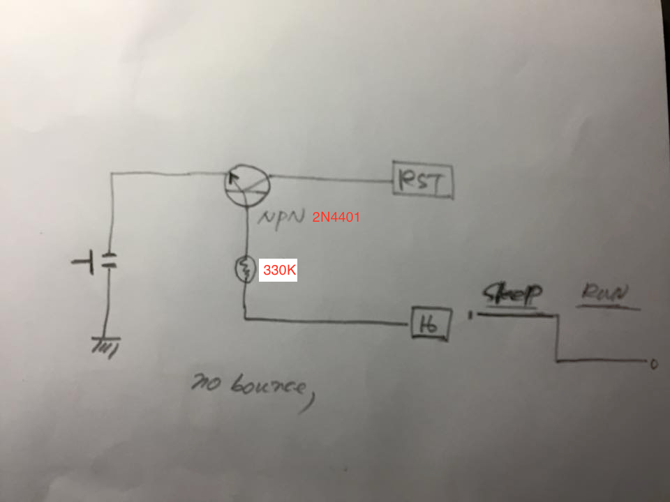
@manishkr-iitg I am using 16 as output on my dash like button. With deepsleep(0), 16 is used to block bounce(on start, going low). |
|
I tested all pins as OUTPUT and everything worked perfect most of the time. However once during a 20 minute period, the esp showed weird behavior as if it was rebooting quickly. Even pressing RESET button didn't help. And all of a sudden, things went normal. During the weird phase, GPIO 16 was going HIGH and LOW randomly after every 200-500 ms. |
|
hi @manishkr-iitg , I have problem to programming ESP-07 ,sometimes is working sometimes is not and not even programmed, can you tell me which IDE setting you were used for and if you have any schematic I really appreciated if you could share it |
|
This is the schematic I am using with 100% success rate. Forget about the GPIO pins and ADC on the right side. You can use them according to your application. However you need to get the left hand side schematics correct. 0.1 uF capacitor should be placed closed to VCC and GND lines. Reset, CH_PD and Flash/IO0 pins must be pulled up with a 10K resistor. Additionally put a fast diode 1N4148 for reset pin protection. You need to pull down GPIO15 with a 10K resistor. GPIO2 should be preferably left open. In case you have to use it, make sure it's open/HIGH during start up. Programming the ESP: You need to Pull the FLASH pin LOW (tie it to GND) and then reset the ESP to send it to programming mode. Then you just need Tx Rx and common GND between programmer and ESP to program the ESP. This can be achieved easily by using 2 tact switches wired to Reset and Flash lines. When pressed, those switches should send a LOW signal to those lines. When you need to enter program mode, hold the switch on Flash line and press the reset switch. Go ahead and program it. Once done, just press the reset switch only and esp comes out of program mode. |

|
Could you explain the diode for protection on the reset? I know sometime zeners are used to protect from the high-voltage programming being triggered on some microprocessors but I don't think that should be the case here? |
|
@RichyT - You are right. Looks like I added the diode due to copy paste error. I was working on arduino schematic where reset pin requires that diode. I implemented the same circuit over here. Rest assured, that diode won't break anything. |
|
No worries. I'm looking at trying to drop an esp-07 into one of those cheap DIY 7-segment clocks so I'm trying to work out the best way to manage the GPIO. I'm thinking I need 4 pins to drive a couple of shift registers then the ADC for the temperature but then there's a light detector, a couple of buttons and a buzzer. I think I can drop the buttons though. I might have just thought of a way to do the two shifts with three pins. Hmm. (Edit: D'oh. Of course, I can just chain them.) And the buzzer is just a buzzer so I can use the shift register for that. I could use the remaining 3 bits to select the button and the light sensor for input... |
|
Closing per #3655 . |
I am working on a project which requires 7 GPIO pins:
2 - i2c
2 - Output
3 - Input (Two inputs can be anything while startup. One input is ensured to be HIGH)
I2C:
I have been using 12 and 13 as SCL and SDA successfully and will prefer not to change that.
Here are my selections for inputs and outputs:
INPUTS:
2 inputs will be regular inputs and can be HIGH/LOW during startup so I am selecting GPIO 4 and 5 for that purpose. Remaining one input is connected to a tact switch and will go LOW only when button is pressed otherwise pulled up. GPIO 2 seemed comfortable with this because it will ensure a HIGH during startup.
OUTPUTS:
14 is one of the output pins and it seems to work perfect. I am confused between 15 and 16 as other output. Initially I felt I shouldn't mess around with 15 because it requires a pull down during startup and I chose 16. But 16 is giving me weird issues, mostly restarting of esp module. Also, I measured using my oscilloscope that 16 is HIGH for 400-450 ms during startup before going LOW. This means my device will turn on for half sec every time esp restarts. After some web search, I came to know that 16 is somehow tied to Reset which allows it to wake up from deep sleep. I tried testing 16 as input. Sometimes it worked and sometimes it rebooted the esp, whenever I gave it a LOW by connecting it to GND.
Is there an easy way to successfully use 16 for input/output? (By changing code. No hardware change.)
Is there any issue with using GPIO 15 as an output?
Is there any better pin allotment for my use case?
Want to back this issue? Post a bounty on it! We accept bounties via Bountysource.
The text was updated successfully, but these errors were encountered: