Passive buzzer guide
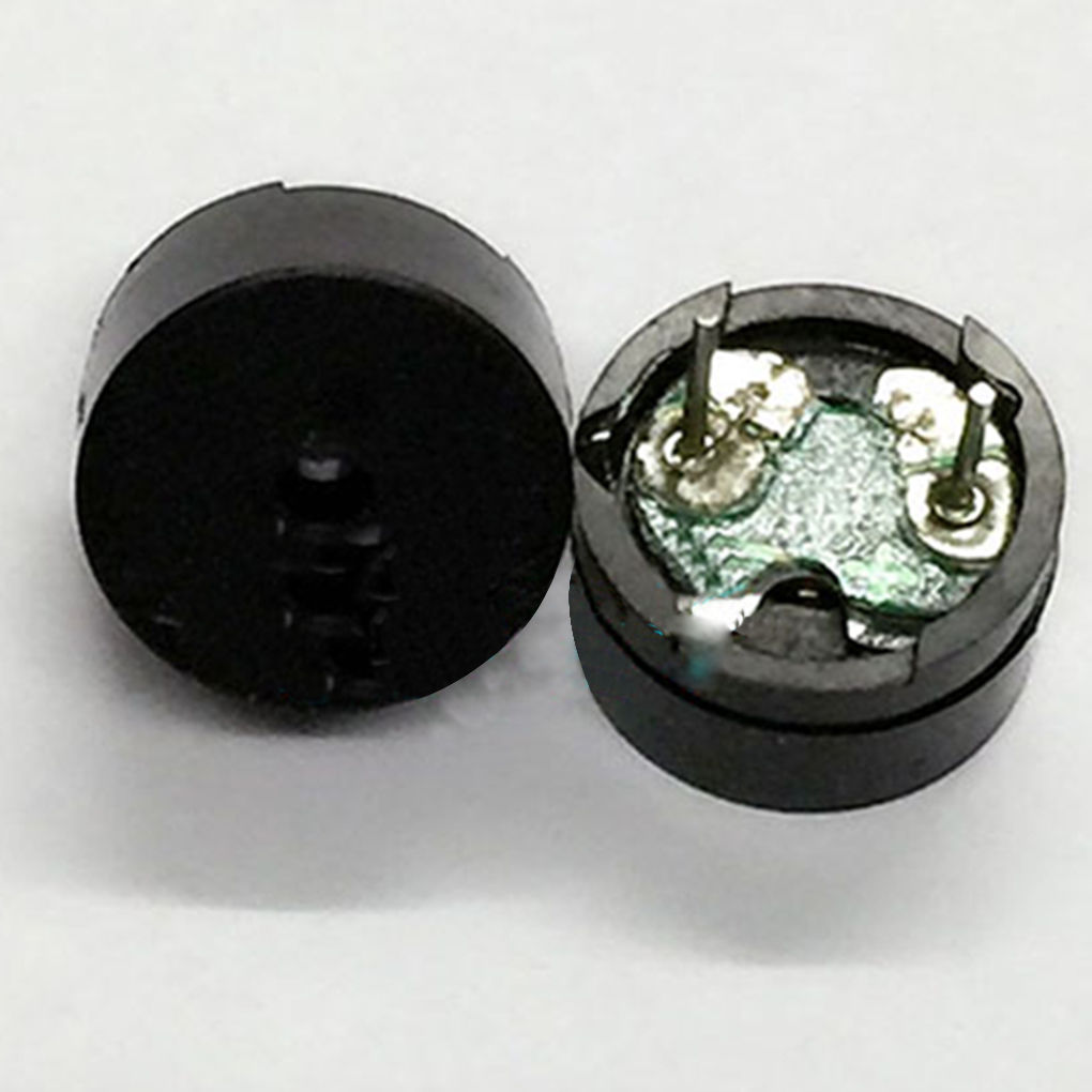
The Fochica devices communicates a lot of information to the user through sound. For this purpose it uses a buzzer, which is an audio signaling device that can generate beeps at various frequencies.
There are two main types of buzzers for hobby use, active and passive. An active buzzer has additional circuitry in it which makes it easier to use but limits the buzzer to only making one type of a sound (tone). An active buzzer only requires DC power source for a beep to be generated.
A passive buzzer (AKA magnetic transducer) can make different tones, but the devices that controls the buzzer has to provide it with an oscillating electronic signal at a desired frequency. The supplied frequency will determine the tone. Supplying just a fixed voltage will generate no sound, except perhaps a slight "tick" at the point when the power source is connected or disconnected from the buzzer.
A passive buzzer is required for a Fochica build. The passive variant was selected because it allows to communicate a wider set of events through a variety of tones.
An Arduino can generate an oscillating signal as required by a passive buzzer. The signal can be emitted at one of the digital pins. However, an Arduino can only provide up to about 40mA of current on each of its pins. For this reason we need to limit the current through the buzzer so not to over-load the micro-controller. A typical 16Ω buzzer can be driven directly from an IO pin by using a 100Ω to 200Ω series resistor. This will translate to an average current of about 10-20mA and peak of 20-40mA (which is less than 40mA).
Using a high value resistor will reduce the current but will also reduce the volume of the sound. If placed in an enclosure, the sound will be quieter. You should match the resistor to the required volume, device and your specific buzzer. You can even use a pot or a rheostat if desired.
For driving the buzzer at lower currents (<40mA peak), use:
- A passive buzzer
- A 100-400Ω series resistor to control volume, 200Ω recommended
If you require a louder sound, or if your buzzer requires higher currents than an Arduino can safely supply you can add a transistor to the circuit. You can always use a DMM to measure how much current your buzzer takes when it is driven through a transistor and compare it to Arduino's max current. When doing the calculations, mind that for the oscillating signal, the measured average current will be half of the actual peak current.
The signal from Arduino will connect to the base of the transistor through a base resistor and will open/close the transistor to allow higher current flow from the power source to power the buzzer. When using a transistor you can use lower value series resistors or you can even try none at all.
Popular buzzers are usually 16Ω and usually take as much as 100mA when making a sound (without an additional series resistor). A transistor that can drive 0.5A will be sufficient to handle the buzzer. Therefore, the recommended components that will be needed for driving the buzzer at max volume with a transistor are:
- A passive buzzer
- A transistor capable of 0.5A or more (NPN preferred but PNP can also be used)
- A 1kΩ resistor for the base of the transistor
- An optional 50-500Ω series resistor to control volume
You can get just a passive buzzer component and wire it with a transistor and/or a resistor,
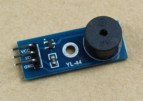
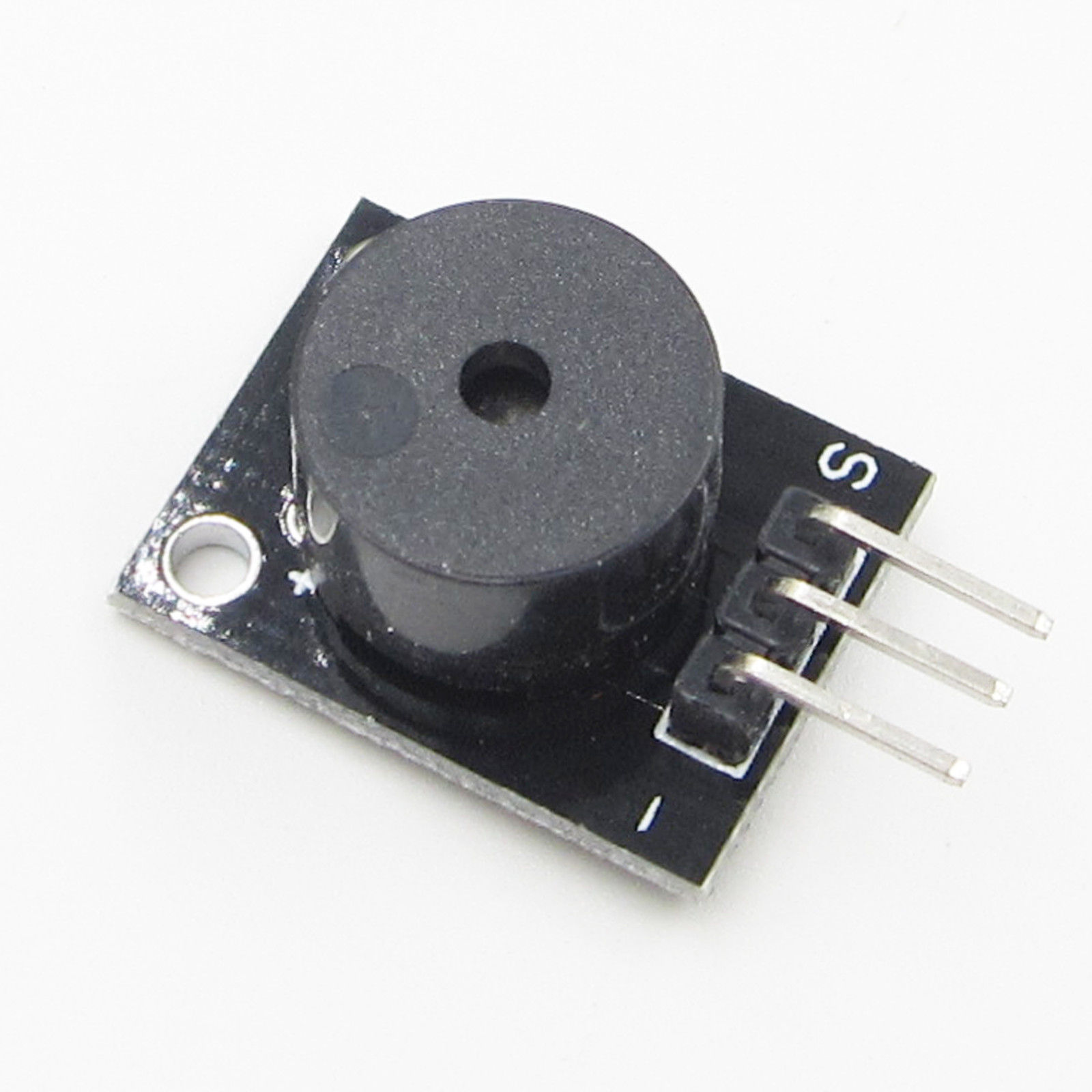
or you can get a ready-made module with all the components.
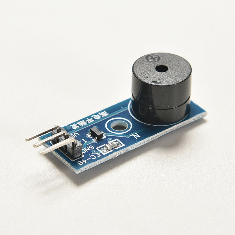
You would go for the individual components directly if you are building your own board or if you can get the parts or already have the parts (these are common). On the other hand, you would go for the module if you are a beginner and are building the device on a breadboard and don't want to mess with the individual components and their wiring.
When shopping online for the module, search for "passive buzzer module", otherwise when shopping for just the buzzer search for "passive buzzer". Note that buzzers, transistors and resistors are cheap components, so they are often sold at bulk for roughly the price of one piece.
Pay attention to the pins of the module. An example above features a module with the pins sticking only partially from the PCB. This may affect your ability to plug the module directly into a breadboard. Other modules may feature male pins sticking up which might or might not fit the way you are planning to assemble your build.
Mind that a module with a buzzer on a PCB doesn't automatically mean that the module has a transistor! If you don't see the transistor on the photo (a small 3 pin SMD part in the images above) assume that this module is just a bare buzzer on a breakout board. This can be true even if the PCB has 3 pins.
The oscillating signal that is generated for the buzzer changes from high to low at a high frequency. For a sound emitting state, it doesn't matter if you have a PNP or a NPN transistor. The type of the transistor does matter for the no-sound state, which is the state most of the time. Though the buzzer will make no sound if a constant current is flowing through it, it does create a waste of power and heats the buzzer since it functions as a resistor. For a proper build, the Arduino has to emit an idle signal that matches the type of the transistor so that the transistor doesn't conduct on idle. For a NPN transistor the Arduino has to emit LOW at idle and for a PNP transistor it has to emit HIGH.
You have to identify the type of the transistor used in your circuit. NPN is the default, so if you are using a PNP then you have to make a customization to your "ConfigVariation". You can edit your configuration or create a copy called "ConfigPrivateVariation". See the "SETTINGS" section of the main Fochica Arduino file. The "ConfigVariation-PrototypeMega1.h" file contains an example of declaring a "getBuzzerOffState" method to support PNP transistors.
Failing to identify and declare your PNP correctly will result in higher power consumption and could drain your battery faster.
To identify the transistor look at the marking on it and search for the matching datasheet online. For example, marking "J3Y" is an SMT S8050 NPN transistor. Marking "2TY" is an SMT S8550 PNP transistor.
If you are looking at an existing module, you can also determine the type based on the way the circuit is wired. An NPN is wired on the "low side", between the buzzer and ground. An PNP is wired o the "high side", between the buzzer and Vcc.
NPN - transistor on the low side
- Emitter to ground
- Collector to - of buzzer
PNP - transistor on the high side, needs low signal at base to conduct
- Emitter to vcc
- Collector to + of buzzer
Diagrams:
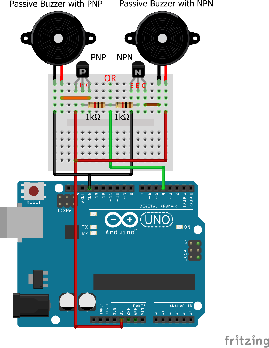
Once wired, cause the device to make a tone. One way to do that is to restart the device, causing a start tune. If there is no tone check your wiring. If the buzzer is "too loud" or if the sound is distorted, try putting a 100Ω or a 200Ω resistor in series with the buzzer to reduce the current.
Copyright © 2017, AY Garage Ltd.
