internal part schematic pin number rotation and movement #3641
Comments
|
@mMerlin "I am guessing this is an example of why @vanepp says not to use svg transforms in the part images. The interesting piece here is that some of the pin text looks fine, others are drastically moved, even though all of the text is wrapped in a single transform. So this part might make a good test case." I haven't done much on the svg export side of things, my usual issue with transforms is in pcb where it sometimes screws up and moves traces out of the view box (meaning they don't show up in gerber output, although they do in Fritzing pcb view.) Unfortunately I don't have a test case that works reliably, I saved one that did this but the part now works correctly when I try it. Something changed, or something needs to be just right in order to trip the error. As I have time I'll poke at this and see if I can get it to reproduce with your part, then remove the transforms and see if that fixes the problem. As well there was a major re write of the svg export and geber code (some 6000 commits) a couple or 3 years ago, that had to be backed out because gerber output was broken. The opinion at the time was the people doing the work where more svg people than gerber people so the svg parts of that may be useful. I usually advise against transforms because they imply an 8*8 matrix multiply at each render, and I have to think that impacts performance. Unfortunately Inkscape loves transforms ... |
|
@vanepp And I like transforms when manually editing svgs, because a simple translate makes all the following numbers (in the block) line up at nice easy multiples of 0.1 inch. Which is why it was used for that part. Since that is just a translate, the math is a lot simpler. If implemented correctly. |
|
I don't actually know for sure if it is a reasonable thing to eliminate transforms. The proof would be to make a part with and without transforms, then instrument the render loop (assuming there is such a thing of course) in Fritzing to time rendering the part 1000 or more times to see if there is a significant performance difference with and without transforms. While it seems to me there should be, it is possible things like GPUs and/or optimizations may make the difference negligible. Also not all transforms can be eliminated, some to do with stroke-widths have to be done at run time it appears. I'd think the web folks would have jumped on eliminating transforms if there was performance to be gained by doing it as well. |
|
Performance is the least of the problems here. Most parts of Fritzing are good to go on ten year old computers, and matrix multiplication is blazing fast. If you see a specific performance problem let me know, I like those. Although I can not justify working on them currently :-) Now, I think a better way is to work with inches: Note the view box size is 445 x 600 , Milimeters will also work, if you prefer that. But I suggest to avoid giving width and height in pixels, because that was an issue even before retina displays were a thing. |
|
@KjellMorgenstern Other than the performance comment, where did the rest of that come from? I don't think anything in this conversation was talking about unusual resolutions. The part that demonstrated the problem has 90 px per inch, configured in the svg element attributes. It does use several transforms (translate only) to keep the graphical element placements at multiples of 9 (for 0.1in spacing), and to keep the coordinates identical for repeated blocks. I like 100 or 1000px per inch for the reasons you give, but would still have the transforms to "align" to grid. When I was learning to create parts, the references I could find kept saying to use 72 or 90. If that has changed, I haven't seen it. |
|
I might have mixed this with comments from other issues. Regarding chaining of transforms: I agree that should be fixed in Fritzing, at some points the code does/did this wrong. Simplifying the transforms in the SVG is a fast and there recommendable workaround. |
|
@KjellMorgenstern "About the resolution / alignment: Although I agree this is somewhat off topic here (I think the part is dimensioned in inches, as FritzingCheckPart.py will complain if the dimension is px) however a slight correction anyway. Older Illustrator (and some older parts in core such as breadboards) are dimensioned in pt (72dpi), Inkscape before version 0.9.1 (I think), used 90dpi (the svg standard at the time), Inkscape 0.9.2 and higher use the current standard of 96dpi for px. Fritzing as you noted tries to guess which dpi value was in use for the svg by looking at the metadata for something and sometimes gets it wrong, which is why FritzingCheckPart gives a warning (probably should be an error though) if the part is dimensioned in px. I don't know what Illustrator is currently using (I would guess 96dpi since that appears to be the current svg standard) but as you note in or mm are safest as there is no ambiguity in the dpi. However setting Illustrator to that appears to be difficult as someone in the forums who uses Illustrator often gets parts dimensioned in px. If we can find someone that uses Illustrator (I don't) and can tell us how to set it to use in or mm as the dimension we should document that (of course when we have documentation ...) Inkscape can rescale a 72dpi document in to a 96dpi one by setting document dimension to pt (72dpi) then adjusting the scale parameter, but it is a bit painful because floating point round off from the rescale often turns circles to ellipses (which in pcb breaks gerber processing which only accepts circles to drill a hole.) It is good to know that transforms are not a performance issues as well. I had no proof one way or the other, but it seemed to me that transforms should be expensive, if not, there are many more things to work on so that is good to know. |
|
@KjellMorgenstern I can easily get rid of the transforms for pin labels for those schematics. It's only 2 files, and the labels are all in wrapped in a single group, so they should be easy to move and adjust. As mentioned in the initial report though, keeping this around could be a good test case when someone is working on the code. It will stay in the repository, so it can always be dug out again later. Outstanding question in this though, is what is the intent for the svg export. Should it be adjusting the text the same as view is doing (attempting to do)? Also, for creating new parts, is it now recommended (at least allowed) to create the images (all views) so that px equals mils? (still with image height and width in inches) Will that cause problems for other people that want to modify or reuse the images with tools that are 'set in their ways'? @vanepp Yes the schematic is already in inches <svg
xmlns="http://www.w3.org/2000/svg"
xmlns:xlink="http://www.w3.org/1999/xlink"
version="1.2"
baseProfile="tiny"
x="0"
y="0"
width="0.811in"
height="0.811in"
viewBox="0 0 73 73"
xml:space="preserve">Also for documentation. This case needs to be added to the part testing process. Place any new part to be added to core, flip it horizontally on the schematic view, and see where any text ends up. Until the code is fixed to that it gets it right. |
|
The problem is not transforms around the part labels in the schematic images. I adjusted the schematic svg images to get rid of those, and the problem still exists. Not quite the same, but still some major miss-placed text. In both 0.9.4b and latest develop version. Here are the adjusted svg files, renamed to append .zip for posting Here are screen shots from version 0.9.4b and 0.9.5. In these, Disp1 is normal, Disp2 is flipped horizontally, Disp3 is flipped vertically, Disp4 is rotated 180° 0.9.4b 0.9.5 The develop version is a lot better, but it is still shifting all text a little incorrectly. I think it is basing adjustments on an incorrect text origin (alignment). That is not the complete answer though, since some of the labels move more, and different directions, than others. |


|
@mMerlin "Also, for creating new parts, is it now recommended (at least allowed) to create the images (all views) so that px equals mils? (still with image height and width in inches) Will that cause problems for other people that want to modify or reuse the images with tools that are 'set in their ways'?" Assuming I'm reading this correctly and you are referring to the viewbox settings, the part file format document recommends (or specifies) exactly what you propose (on the about svgs section near the bottom of the document): "For example, many Fritzing files use inches as units, and use 1000 dpi as the basis for the viewBox. So you might see something like In other words, when you are looking at individual SVG elements like or , their coordinates will be expressed relative to the viewBox and their effective units will be in 1000 per inch increments." In Inkscape 0.9.4 you can achieve that by setting the scale to 10.41667 which will produce the correct viewbox settings when you resize document to page. Procedure described here: https://forum.fritzing.org/t/rescale-a-svg-using-inkscape/7581 I don't know of anything that objects to you doing this, although there may well be something. The latest FritzingCheckPart.py (not yet finished) issues a warning if this is not truer which could be and perhaps should be upgraded to an error. |
|
I reviewed that section of Part file format. I remember most of that, but not the 1000 dpi reference. The document has not been modified, so it is something that slide past in all of the 72 and 90 dpi references. Looks like the template files that are in the download with the fonts need updating. From the Download fonts and templates page, download .zip file link. They were all created with Adobe Illustrator, and are using raw px units. That is not in the repository, so a pull request can not be used to fix it. BreadboardViewGraphic_Template.svg <svg version="1.2" baseProfile="tiny" xmlns="http://www.w3.org/2000/svg" xmlns:xlink="http://www.w3.org/1999/xlink" x="0px"
y="0px" width="595.275px" height="841.89px" viewBox="0 0 595.275 841.89" xml:space="preserve">PCBViewGraphic_Template.svg <svg version="1.1" id="Layer_1" xmlns:xml="http://www.w3.org/XML/1998/namespace"
xmlns="http://www.w3.org/2000/svg" xmlns:xlink="http://www.w3.org/1999/xlink" x="0px" y="0px" width="30.24px" height="30.24px"
viewBox="0 0 30.24 30.24" enable-background="new 0 0 30.24 30.24" xml:space="preserve">SchematicViewGraphic_Template.svg <svg version="1.2" baseProfile="tiny" id="Layer_1" xmlns="http://www.w3.org/2000/svg" xmlns:xlink="http://www.w3.org/1999/xlink"
x="0px" y="0px" width="57.643px" height="71.833px" viewBox="0 0 57.643 71.833" xml:space="preserve"> |
|
Pin 11 obviously behaves different, which will be a good pointer to develop a fix. |
|
The flipped horizontal instance looks like all of the labels were centred over initial position coordinates, but the original uses The horizontal positioning of all of the labels in the flipped vertical instance looks correct. Pins 1, 12, 14, 11 look like they also have the correct vertical position. The rotated instance has the same issue with horizontal position as the flipped horizontal case. Centred over what should be start or end position. Like the flipped vertical instance, pins 1, 12, 14, 11 look like they have the correct vertical position. Or at least a lot closer than the rest. |
Current Behaviour
Rotating a (specific) part by 180° in schematic view messes up some (but not all) of the internal (to the part) pin number labels. I believe this is part of the code to attempt to get the schematic internal part text the right way up, regardless of the rotation of the part itself. I am guessing this is an example of why @vanepp says not to use svg transforms in the part images. The interesting piece here is that some of the pin text looks fine, others are drastically moved, even though all of the text is wrapped in a single transform. So this part might make a good test case.
This has been partially fixed in the latest develop version. Some of the text is still moved, but not nearly as badly.
In both 0.9.4b and 0.9.4, the exported svg image is different again. There, the pin labels are not adjusted at all, so they retain the rotation of the part itself. Which right now, for me, is a 'good thing'™
0.9.4b not rotated

0.9.4b rotated 108°

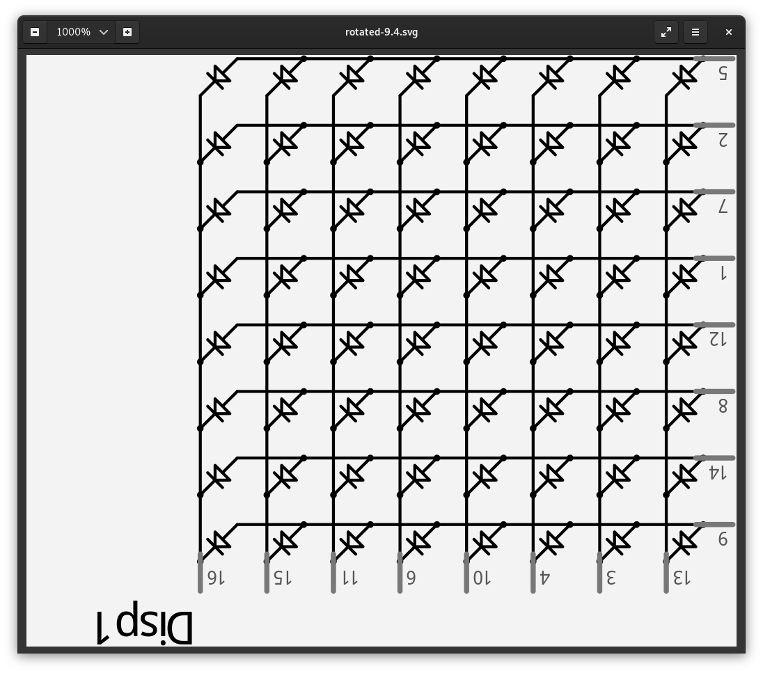
0.9.4b exported svg, renamed to append .zip to the name
rotated-9.4.svg.zip
0.9.4b snapshot of rotated exported svg
0.9.5 not rotated

0.9.5 rotated 108°

0.9.5 exported svg, renamed to append .zip to the name
rotated-9.5.svg.zip
0.9.5 snapshot of rotated exported svg

Build:
Fritzing version 0.9.4.2019-12-01.CD-498 - Qt version 5.13.2
latest 0.9.5 devel build
Operating System:
NAME=Fedora
VERSION="31 (Workstation Edition)"
ID=fedora
VERSION_ID=31
VERSION_CODENAME=""
PLATFORM_ID="platform:f31"
PRETTY_NAME="Fedora 31 (Workstation Edition)"
ANSI_COLOR="0;34"
LOGO=fedora-logo-icon
CPE_NAME="cpe:/o:fedoraproject:fedora:31"
HOME_URL="https://fedoraproject.org/"
DOCUMENTATION_URL="https://docs.fedoraproject.org/en-US/fedora/f31/system-administrators-guide/"
SUPPORT_URL="https://fedoraproject.org/wiki/Communicating_and_getting_help"
BUG_REPORT_URL="https://bugzilla.redhat.com/"
REDHAT_BUGZILLA_PRODUCT="Fedora"
REDHAT_BUGZILLA_PRODUCT_VERSION=31
REDHAT_SUPPORT_PRODUCT="Fedora"
REDHAT_SUPPORT_PRODUCT_VERSION=31
PRIVACY_POLICY_URL="https://fedoraproject.org/wiki/Legal:PrivacyPolicy"
VARIANT="Workstation Edition"
VARIANT_ID=workstation
Steps to reproduce:
20mm_8x8_dot_matrix_column_cathode_led_display_narrow_pad.fzp
Expected Behaviour
text should move consistently
The text was updated successfully, but these errors were encountered: